• Skip to primary navigation
  • Skip to main content
  • Skip to primary sidebar

Circuit Ideas for You

Get free circuit ideas online.

  • Home
  • Privacy Policy
  • About
Home » 50Hz Square Wave Generator Circuit using Transistors

50Hz Square Wave Generator Circuit using Transistors

Last updated on 4 July 2026 by Admin-Lavi Leave a Comment

This article is for 50Hz Square Wave Generator Circuit using Transistors, here, two transistors switch ON and OFF one by one and outputs blink opposite time.

We used no ICs; we require only simple components, and this circuit also helps us understand the basic working of an oscillator.

Also, we can change the resistor or capacitor values to adjust the speed.

Circuit Working:
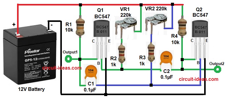
50Hz Square Wave Generator Circuit  Diagram using Transistors

Parts List:

ComponentsValuesQuantity
Resistors10k 1/4 watt2
1k 1/4 watt2
Preset 220k2
CapacitorsCeramic 0.1µF2
SemiconductorsNPN Transistor BC5472
Battery / Power Supply 12V DC1

When power supply is ON the circuit start by itself and due to small difference, one transistor turn ON first, then its output become active and other transistor stays OFF.

After that, capacitor connected to ON transistor start charging and after some time the capacitor discharge to other transistor base; this make second transistor ON and first transistor OFF.

Now second capacitor start charging and after delay, it discharge back and turn first transistor ON again and this switching continue again and again.

Hence, because of this, square wave output generate and both outputs work opposite time.

How to Build:

To build a 50Hz Square Wave Generator Circuit using Transistors follow the below connection steps:

  • First, assemble all parts as per circuit diagram.
  • Next, emitter pin of Q1 and Q2 both connect to ground, collector of Q1 connects with R1 and C1 and collector of Q2 connects with R4 and C2.
  • Then base of Q1 connects with C2 and VR1 through resistor R2 and also base of Q2 connects with C1 and VR2 through resistor R3.
  • Now R1 and R4 connect from +12V to collectors and VR1 and VR2 connect from +12V to transistor bases.

Conclusion:

Overall, this simple and low cost 50Hz Square Wave Generator Circuit using Transistors uses only basic parts and circuit is easy to make and understand.

Furthermore, output frequency depends on resistor and capacitor and by changing RC value, different frequency we can get.

Filed Under: DIY Projects, Oscillator Circuits, Transistor Circuits

About Admin-Lavi

Lavi is a B.Tech electronics engineer with a passion for designing new electronic circuits. Do you have questions regarding the circuit diagrams presented on this blog? Feel free to comment and solve your queries with quick replies

Previous Post: « Transistor Based LED Alternator Blinker Circuit
Next Post: Mini Condenser Microphone Amplifier Circuit »

Reader Interactions

Leave a Reply Cancel reply

Your email address will not be published. Required fields are marked *

Primary Sidebar


Categories

  • 555 Timer Projects (137)
  • Alarm Circuits (81)
  • Amplifier Circuits (94)
  • Arduino Projects (103)
  • Audio Circuits (189)
  • Automation Circuits (150)
  • Automobile Circuits (40)
  • Battery Charger Circuits (88)
  • DIY Projects (435)
  • Free Energy (12)
  • Heater and Temperature Controllers (32)
  • High Voltage (24)
  • Hobby Circuits (241)
  • Indicator Circuits (63)
  • Inverter Circuits (17)
  • IoT projects (12)
  • LDR Circuits (47)
  • LED and Lamps (201)
  • Meters and Testers (44)
  • Mini Projects (390)
  • Motor Controllers (26)
  • Oscillator Circuits (70)
  • Power Supply Circuits (244)
  • Radio Frequency (8)
  • Remote Control Circuits (12)
  • Renewable energy (20)
  • Security and Protection (128)
  • Sensors and Detectors (236)
  • Solar Circuits (31)
  • Timer Circuits (63)
  • Transistor Circuits (178)
  • Transmitter Circuit (19)
  • Tutorials (33)
  • Voltage Regulator (55)
  • Water Level Controller (10)

Recent Posts

  • Low Current Controlled Battery Charger Circuit using LM723 IC
  • 741 Op-Amp Treble Booster Circuit
  • Simple Diode and Transistor Based Audio Limiter Circuit
  • Simple 500mW Speaker Driver Circuit
  • Easy DIY LM386 Audio Amplifier Circuit

Recent Comments

  1. Admin-Lavi on High Voltage Fence Charger Circuit
  2. etere on High Voltage Fence Charger Circuit
  3. Admin-Lavi on High Voltage Fence Charger Circuit
  4. egidio grzinic on High Voltage Fence Charger Circuit
  5. Logic OR Gate Circuit using Transistors - Circuit Ideas for You on Automatic Street Light Circuit using LDR

Copyright © 2026 | New Circuit Ideas