The 7805 is very popular voltage regulator IC, as it gives fixed 5V output and is easy to use.
But it has one problem the output current is limited, because it normally gives around 1A maximum current.
Sometimes we need more current for our motors, relays or microcontroller project with many modules.
To solve this problem we need current booster circuit, and this circuit increases current capacity, but voltage remains 5V.
In this 5V High Current Power Supply Circuit using IC 7805 we use two PNP transistors as they help to share load current, which helps IC 7805 stay safe.
Now, below we will learn how to increase or boost the output current of 7805 voltage regulators with the help of PNP transistors.
Circuit Working:
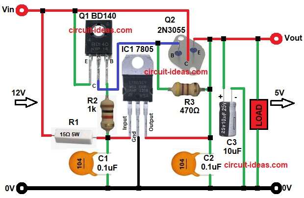
Parts List:
| Components | Values | Quantity |
|---|---|---|
| Resistors (All resistors are 1/4 watt unless specified) | 15Ω 5 watt, 1k, 470Ω | 1 each |
| Capacitors | Ceramic 0.1uF | 2 |
| Electrolytic 10uF 25V | 1 | |
| Semiconductors | Voltage Regulator IC 7805 | 1 |
| PNP Transistor BD140 | 1 | |
| Power Transistor 2N3055 | 1 | |
| Heat sink if required for 7805, BD140, 2N3055 | 1 each |
Circuit starts, by giving 12V DC at input and this goes to IC 7805 regulator which converts 12V to 5V.
But this 5V is low current for that we need to add transistor at booster stage.
Q1 is BD140 PNP transistor and it senses voltage drop, when load current increases a small voltage drop appears and this drop turns ON Q1 transistor.
Then Q1 drives Q2 and this Q2 is 2N3055 power transistor which handles high current, so most load current flows through Q2.
7805 gives only small base current and therefore, 7805 does not heat much.
In the diagram R3 limits base current and R2 controls biasing, C1 and C2 remove noise and C3 stabilizes output voltage.
Thus we get 5V output, but if current is higher than 1A depending on transistor and heat sink, it can go upto 3A to 5A.
Formula with Calculation:
Power Dissipation in Transistor 2N3055:
P = (Vin – Vout) x Iload
Example:
- Vin is 12V
- Vout is 5V
- Iload is 4A
Then our calculation is:
P = (12 – 5) x 4
P = 7 x 4
P = 28W
So transistor must handle 28W, so a large heat sink is required.
How to Build:
To build a 5V High Current Power Supply Circuit using IC 7805 follow the below connection steps:
- Start, the circuit by gathering all the circuit parts as shown in above circuit diagram.
- Then start with IC 7805 Input pin which connect to the junction of resistor R1, R2 and capacitor C1.
- Ground pin of IC connects to common ground 0V.
- Output pin of IC connects to R3 resistor one end and also connect C2 capacitor one end.
- Then start with PNP Transistor Q1 BD140 emitter pin connects to Vin input supply.
- Base pin connect to R2 and R3 network.
- Collector pin connect to base of Q2 and resistor R3 one end.
- Then start with power Transistor 2N3055 emitter pin connect to Vout of 5V.
- Base pin connect to collector of Q1.
- Collector pin connect to Vin input supply.
- Capacitors C1 connect between input pin of IC and ground.
- C2 connect between output pin of IC and ground.
- Finally, C3 connect across Vout and ground.
Note:
- Transistor 2N3055 large heat sink is needed.
- IC 7805 a small heat sink is required.
- Transistor BD140 a small heat sink required if current goes high.
Conclusion:
This 5V High Current Power Supply Circuit using IC 7805 is simple solution for increasing output current easily.
Voltage remains stable at 5V and two PNP transistors share load due to which IC 7805 stays protected, but heat sink is very important.
Therefore, this circuit is good for medium power project, because if high efficiency is needed then SMPS is better.
Still for learning and hobby this design is very useful.