This project is for smart LDR Light Sensor Circuit with Arduino, it can feel light like human eye.
When dark come, it turn ON lamp by itself and when light come, it turn OFF lamp automatic; so no need to press any switch.
Also, it save time and save power and it is small, simple and very low cost system.
Arduino Code:
int LDR = A0;
int relay = 8;
int value = 0;

void setup() {
  pinMode(relay, OUTPUT);
  Serial.begin(9600);
}

void loop() {
  value = analogRead(LDR);
  Serial.println(value);
  if (value < 300) {
    digitalWrite(relay, HIGH);
  } else {
    digitalWrite(relay, LOW);
  }
  delay(500);
}
Coding Explanation:
- LDR analog pin is A0.
- Relay pin is 8.
- Arduino read analog value from A0.
- In dark it value is low.
- If value is below 300 then relay turns ON.
- Relay ON will turn ON the lamp.
- If value above 300 then relay turns OFF.
- Relay OFF will turn OFF the lamp.
Circuit Working:
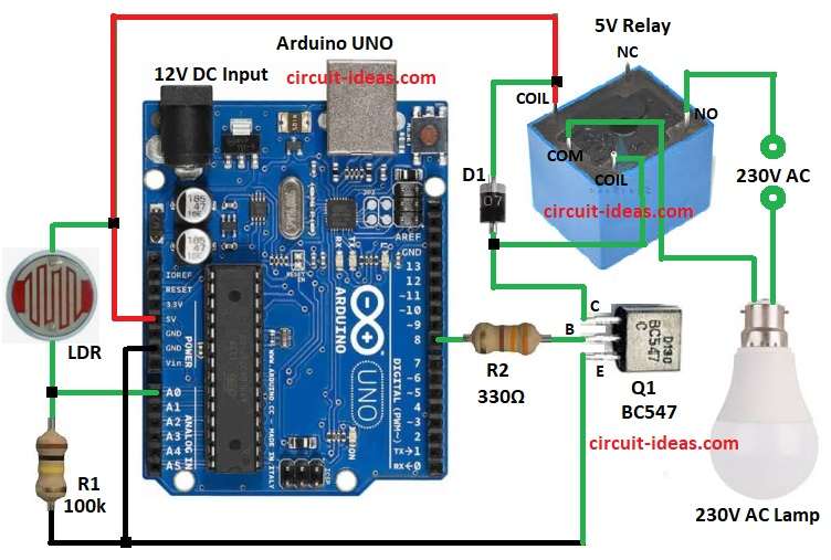
Parts List:
| Components | Values | Quantity |
|---|---|---|
| Resistors | 100k 1/4 watt | 1 |
| 330Ω 1/4 watt | 1 | |
| LDR standard type | 1 | |
| Semiconductors | Arduino UNO Board | 1 |
| Transistor BC547 | 1 | |
| Relay 5V | 1 | |
| Diode 1N4007 | 1 | |
| LED Bulb 230V AC | 1 |
LDR and resistor make voltage divider and also LDR change resistance with light.
In dark, LDR resistance go high and voltage is at A0 go low, then Arduino read low voltage and it send HIGH to transistor base.
After that transistor turn ON like switch and a big current go to relay coil and then relay turn ON and give power to lamp and lamp glows.
Furthermore, in light, LDR resistance go low and voltage at A0 go high and then Arduino read high voltage and it send LOW to transistor base.
Now transistor turn OFF, no current go to relay coil and relay turn OFF and cut lamp power and then lamp goes OFF.
Therefore, this is how it work automatic with light and dark.
Formula with Calculation:
LDR and resistor form a voltage divider.
Vout = (R1 / (R1 + RLDR)) * 5V
In dark, RLDR is high so Vout is low and in light, RLDR is low so Vout is high.
Example:
Dark: RLDR = 1M = Vout = 0.45V
Light: RLDR = 10k = Vout = 4.54V
How to Build:
To build a LDR Light Sensor Circuit with Arduino follow the below steps:
- First, take all parts from circuit.
- Next, connect LDR to 5V and GND with 100k resistor.
- Then connect middle point to A0 pin.
- Now connect other coil side to 5V, connect relay common to AC supply and connect relay NO to lamp.
- Join Arduino GND and relay GND.
- Also, connect transistor base to pin 8 through 330 ohm.
- After that, connect transistor emitter to GND and connect transistor collector to relay coil pin through diode D1.
Conclusion:
To conclude, LDR light sensor circuit with Arduino work good to detect light level; also LDR value change when light increase or decrease and Arduino read this value and do action.
Hence, this project simple and useful for automatic light control and light monitoring system.

Leave a Reply