There are few protection circuit which we have shown in our previous post, but this article is for Simple 12V Protection and Soft Start Circuit for 12V systems.
It helps to protect our load from sudden high current and voltage spikes and also, it gives a smooth start when power turns ON, because of this, the circuit increases the life of our devices.
This circuit is small, very easy to build and we can use this circuit in power supplies, battery systems and small electronic projects.
Circuit Working:
Parts List:
| Components | Values | Quantity |
|---|---|---|
| Resistors | 1k, 3.3k 1/4 watts | 2 |
| Semiconductors | Transistor 2N2222 | 1 |
| Diode 1N4148, 1N4007 | 1 each | |
| Relay 12V SPDT | 1 | |
| LED Standard any | 1 | |
| Power Supply 12V DC | 1 |
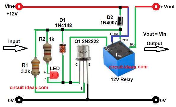
At first, we must apply 12V input to the circuit, then current flows through resistor R2 and LED and this LED starts glowing, so it shows power ON.
Next, transistor Q1 2N2222 controls the 12V relay and at the beginning, capacitor effect and resistor network delay the base voltage of Q1.
So, Q3 does not turn ON immediately, because of this, the relay stays OFF for a short time.
Meanwhile, diode D1 and D2 protect the circuit from reverse voltage and spikes, after some delay, base voltage increases slowly and then Q1 turns ON.
Now, current flows through relay coil, so relay gets energized and finally, the NO (Normally Open) contact closes and connects Vin to Vout, in this way, the circuit gives a soft start instead of instant connection.
After the relay turns ON, the output voltage becomes approximately equal to the input voltage (Vout = Vin).
If any fault or sudden voltage issue happens, diode and resistor network protect the transistor and relay and therefore, the circuit improves safety.
How to Build:
To build a Simple 12V Protection and Soft Start Circuit following are the connection steps one needs to follow:
- First, the circuit starts by assembling all the circuit parts as in diagram above.
- Then connect Vin 12V to one end of relay contact and diode D2.
- Then connect the other side of relay NO pin to Vout.
- Now connect relay coil pin one side to 12V line through diode D2 cathode.
- Next, connect other side of relay coil pin to collector of transistor Q1 and anode of diode D1.
- Then connect emitter of Q1 directly to ground.
- After that, connect base of Q1 to one end of resistor R1 and other end of R1 connect to one end of R2, cathode of diode D1 and relay coil pin.
- Connect resistor R2 and LED in series for indication as shown in circuit diagram.
- Finally, connect all grounds together to common GND.
Conclusion:
This Simple 12V Protection and Soft Start Circuit gives simple and effective protection with soft start feature.
It reduces sudden current flow and protects connected devices and also, it is easy to build and uses low cost components.
Therefore, beginners can easily use this circuit in many 12V applications.
Leave a Reply