This simple Low Noise Transistor Preamplifier Circuit increases very small audio signals like microphone or weak music signals.
Here, the circuit uses two transistors:
- One NPN BC549 transistor which is better for audio because it has lower noise, designed specially for audio applications and gives cleaner signal output.
- Second is PNP BC559 transistor which gives lower noise and is also better for audio quality.
Also, after the preamplifier, the signal becomes strong and we can send it to a power amplifier, as this circuit costs low, is easy to make and suits beginners.
Circuit Working:
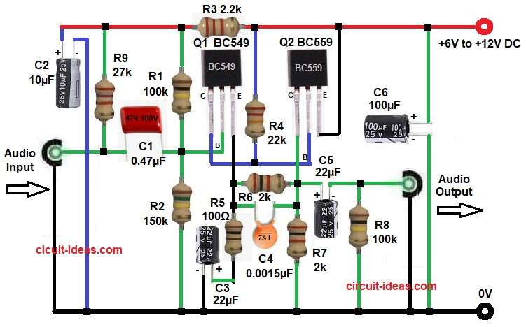
Parts List:
| Components | Values | Quantity |
|---|---|---|
| Resistors | 150k, 2.2k, 22k, 100Ω, 27k | 1 each |
| 100k, 2k | 2 each | |
| Capacitors | Electrolytic 10µF 25V, 100µF 25V | 1 each |
| Electrolytic 22µF 25V | 2 | |
| Ceramic 0.0015µF | 1 | |
| PPC 0.47µF 100V | 1 | |
| Semiconductors | Transistors BC549 NPN, BC559 PNP | 1 each |
| Power Supply DC +6V to +12V | 1 |
To begin with, supply voltage enters the circuit from 6V to 12V and then, audio signal comes to the input terminal.
Capacitor C1 blocks DC voltage and allows only AC audio signal to pass into the circuit.
After that, signal goes to base of Q1 BC549 and resistors R1 and R2 create proper bias voltage for Q1.
As a result, because of this biasing, Q1 works in active region and amplifies the weak signal.
After that, emitter resistor R5 controls current of Q1 and capacitor C3 increases gain by bypassing AC signal.
Then, amplified signal from Q1 goes directly to second transistor Q2 BC559 and this connection is DC coupling, so signal transfers without capacitor.
Resistors R4, R6 and R7 set bias and control operation of Q2 and this Q2 further amplifies the signal and makes it stronger.
Capacitor C4 helps in stability and smooth signal transfer between stages.
After that, output signal comes from emitter of Q2 and passes through capacitor C5 and this C5 blocks DC and sends only amplified AC signal to output terminal.
Also, capacitor C6 filters noise from the power supply and keeps the output clean and resistor R9 provides bias voltage for a condenser microphone if used and we can remove R9 from the circuit if we do not need microphone bias.
How to Build:
To build a Low Noise Transistor Preamplifier Circuit follow the below connection steps:
- First, gather all the circuit parts as in diagram above.
- Next, take transistor Q1, collector connect to R4 and Q2 base network.
- Then base pin connect to junction C1 and R1, R2.
- After that, emitter pin connect to to ground with one end of resistors R5 and R6 and capacitators C3 and C4.
- Next take, transistor Q2 BC559 and connect collector pin to ground through one end of resistor R6, R7 and capacitator C5 and C4.
- Then take pin base and connect between resistor R4 and collector of transistor Q1 and pin emitter goes to positive supply.
- After that connect capacitor C2 from positive supply and ground.
- Last capacitor C6 connect from positive supply and ground.
- Then connect resistor R3 at positive supply between resistor R2 and R4.
- Connect resistor R8 between capacitator C5 positive and audio OUTPUT and ground.
- Last resistor R9connect from positive supply and between Audio INPUT and capacitor C1
Conclusion:
This simple Low Noise Transistor Preamplifier Circuit gives good amplification for small audio signal, as it uses easily available components.
Circuit is easy to build and good for learning transistor amplifier and we can use it before power amplifier for better sound.
Hence, this circuit is useful in microphone, small audio projects and DIY electronics.
Leave a Reply