No need to buy costly new speakers.
This Simple Surround Sound Speaker Circuit in this article show how to make surround sound better, it also uses something call Hafler circuit made by man name David Hafler.
So just turn one knob and place speakers right and then sound from front and back speakers get louder.
What is a Surround Sound Speaker Circuit:
Surround sound circuit is type of electric circuit that makes sound feel 3D and full mostly in home theater and multi speaker system.
Also, this circuit sends sound signals to many speakers and puts in different place in room, which helps to give sound more direction and power.
Working of Surround Sound Speaker Circuit:
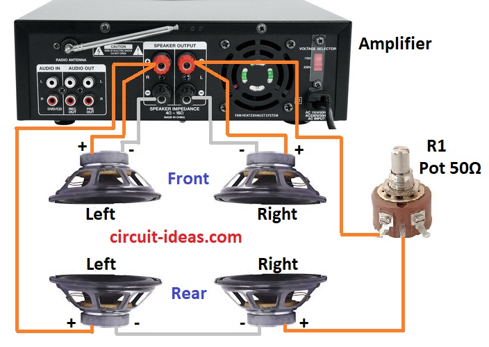
Parts List:
| Components | Values | Quantity |
|---|---|---|
| Potentiometer | 50Ω | 1 |
| Amplifier | Any 4 channel amplifier | 1 |
| Speakers | As per amplifier wattage | 4 |
Firstly, Hafler circuit is easy to set up and use.
Rear left and right speakers get same L-R signal, if sound not good then can remove R1.
Here, many systems are not loud enough anyway.
Also, one rear speaker is okay but it must be 8 ohm or more so amp does not get too much load.
Mostly, for better echo sound put speaker in center and face it up or to back wall.
How to Build a Surround Sound Speaker Circuit:
Need little bit of electronics knowledge to make surround sound circuit.
How to connect Hafler Circuit:
- First, follow Hafler way to wire left and right rear speakers.
- Then add R1 potentiometer like shown in circuit diagram.
Connect to amplifier:
- After that, join amplifier with surround circuit and be sure plus and minus wires connect to right places.
Set up rear speaker:
- Next, connect amp to rear speaker and put rear speaker in back center and face up or to back wall.
Optional ON/OFF switch:
- If want control back sound then we can add ON/OFF switch.
Enhanced Surround Sound Speaker Circuit Definition:
For better surround sound circuit in easy words is sound circuit that gives more good things and best sound feeling than normal simple one.
Working of Enhanced Surround Sound Speaker Circuit:
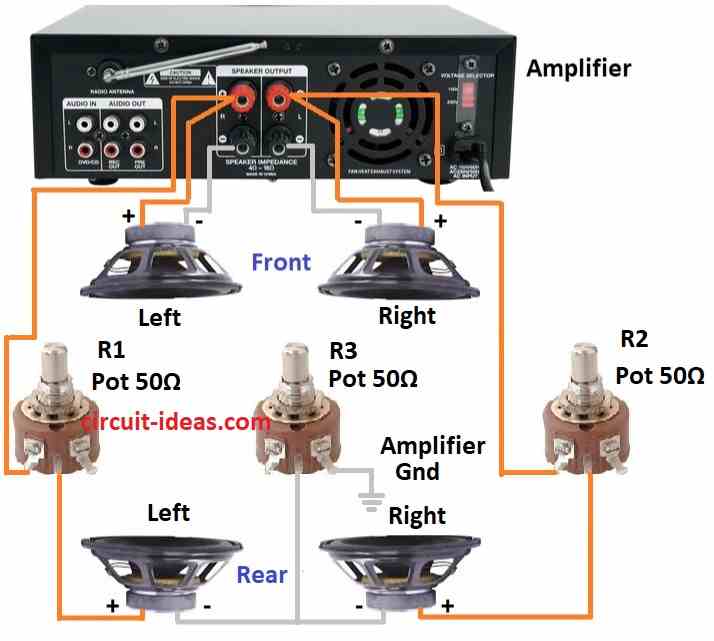
Parts List:
| Components | Values | Quantity |
|---|---|---|
| Potentiometers | 50Ω | 3 |
| Amplifier | Any 4 channel amplifier | 1 |
| Speakers | As per amplifier wattage | 4 |
This circuit may work better for rock music than jazz, as it gives more surround sound feeling than last one.
So, to get good balance from front to back, turn R1 and R2 at the same time, also the user can then sit in one place and adjust R1 and R2 as needed.
Also, while listening turn R3 so front left and right sound goes soft into back speakers and if want to stop sound from mixing in back put ON/OFF switch at X.
Furthermore, if amp have A and B switch for extra speakers then connect rear speaker circuit (a) or (b) to B+ terminal and in this way turning back sound ON or OFF is easy.
Formulas:
David Hafler is well-known man who help make better audio amps and high quality sound systems.
In a surround sound speaker circuit, the amplifier powers many speakers, which helps keep the sound balanced and clear while also protecting the audio quality.
How to Find Power:
To know how much power one speaker needs:
P = VRMS² / R
where:
- P is power in watts
- VRMS is voltage across speaker
- R is speakers resistance like 4 or 8 ohm depends on amp
Balance Formula:
Also, if we want to make the sound of two channels equal with a knob, we must use a potentiometer with the following formula:
Vout = Vin × Rpot / (Rpot + Rfixed)
where:
- Vout is output from amp
- Vin input sound
- Rpot is knobs resistance
- Rfixed fixed resistor value
Speaker Matching Impedance:
Hence, if using many speakers we must give amp right impedance load.
For speakers at same time (parallel):
1 / Rtotal = 1 / R1 + 1 / R2 + …
For speakers one after other (series):
Rtotal = R1 + R2 + …
Be sure total impedance is okay for amp to work safe and through this easy way helps people to learn basic setup for surround sound system and how to spread music to many speakers.
Also, to make full system great we must follow all the above steps right.
How to Build Enhanced Surround Sound Speaker Circuit:
To build a Enhanced Surround Sound Speaker Circuit follow the connection steps below:
Change Hafler Setup:
- First, make surround sound better by changing Hafler setup which depends on what design we need.
Adjust Potentiometers:
- Then turn R1 and R2 together to get good front and back sound balance.
- Also, while hearing music adjust R3 so front left and right sound mixes into back speakers nicely.
Optional ON/OFF Switch:
- If no switch is already there then we can add ON/OFF switch to control back channel sound mix.
Connect to Amplifier:
- Furthermore, if amp have A/B switch connect back speaker circuit to B+ terminal and this make it easy to turn back sound ON or OFF.
Conclusion:
Overall, for making a Simple Surround Sound Speaker Circuit always be safe and check all wires two times to stop the damage.
Moreover, if anyone do not know how to install or set up surround sound then better to ask person who know or get expert help.

Leave a Reply