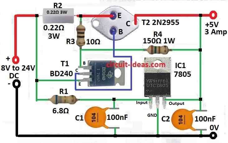
This High Current IC 7805 Voltage Regulator Power Supply Circuit tell how to make one circuit for strong power supply using one chip name LM7805 and this chip take high voltage and give out stable 5V power for devices.
But normal LM7805 give only small current which is not enough for big device.
So in this circuit we have used LM7805 in special way to give more current for device which need little more power; but this circuit uses high voltage so it is little bit dangerous.
Hence, better if one expert electrician do this job and also one adult must stay and watch always, as new people or beginner no should try this project.
Circuit Working:
Parts List:
| Components | Quantity |
|---|---|
| Resistors (All resistors are 1/4 watt unless specified) | |
| 6.8Ω | 1 |
| 10Ω | 1 |
| 0.22Ω 3W | 1 |
| 150Ω | 1 |
| Capacitors | |
| Ceramic 100nF | 2 |
| Semiconductors | |
| IC 7805 | 1 |
| Transistor BD240 | 1 |
| Transistor 2N2955 | 1 |
To begin with, voltage regulator ICs with 3 pins like LM7805 and LM7812 are very good for using in voltage regulator circuit.
But if we want more current, up to 3A, we need to add another transistor called T2 to the circuit.
Old circuit designs had a major problem: they generated too much heat during a short circuit; also this new circuit solves that problem.
Therefore, this new design uses smart electronic idea to stop big current when short circuit happen so it does not become too hot.
When we test this circuit and make output short then only around 0.5A current comes, so there is no overheating happen and in this DC voltage regulator T1 work like current limiter.
If voltage on R2 and R3 goes more than 0.6 to 0.7 volt then T1 turn ON and stop current going to T2; how much voltage needed to stop short circuit depend on value of R2 and R3 together.
Also, R3 and R4 work like voltage divider for T2.
Formula:
Before making high current power supply using IC 7805 we must check if 7805 can give needed current without becoming too hot.
IC 7805 is simple linear voltage regulator which gives fixed 5V from bigger voltage.
Things to remember and formula:
Input Voltage:
Input voltage (Vin) must be more than output 5V + dropout voltage of 7805 and dropout voltage is usually 1V to 2V.
Also, the result depends on how much current the circuit uses and which 7805 regulator we are using.
Current Check:
See how much current our circuit needs from 5V side and that is the output current (Iout); also check if 7805 can give that much current and does not cross its limit or get too hot.
Power Loss:
IC 7805 make heat and this heat is:
Pdiss = (Vin − 5V) * Iout
If this number is big then we need heat sink to cool it.
where:
- Vin is the input voltage
- Vout is the output voltage which is always 5V from 7805
- Iout is the output current
Use heat sink with proper power dissipation (Pdiss) and thermal resistance to make it safe.
Example:
We need 5V power and 3A current.
Vin = 12V like from transformer
Vout = 5V
Iout = 3A
Power loss: Pdiss = (12V − 5V) * 3A = 21W
So IC 7805 will make 21W heat.
To keep IC cool need big heat sink with small thermal resistance.
Hence, by using these simple calculations we can make strong high current power supply with 7805 and we can also change parts and values if our voltage or current is different.
How to Build:
To build a High Current IC 7805 Voltage Regulator Power Supply Circuit follow the below mentioned easy steps for connections:
Layout Design:
- First, think where to put all parts on breadboard and if want to make permanent then make PCB design.
Connect Voltage Regulator IC:
- Next, put LM7805 or LM7812 on board and connect power input to input pin and ground to ground pin.
- Give unregulated voltage to input pin and output pin goes to load and device which need power.
Add Transistor T2:
- Then place T2 transistor on board.
- Connect collector of T2 to output pin of voltage regulator, connect emitter of T2 to ground and connect base of T2 to right place in circuit.
Add Resistors:
- After that, put resistors R1, R2, R3 and R4 on board same as circuit diagram and then connect them same way like shown in schematic.
Connect the Circuit:
- Follow schematic and connect all parts with wire or PCB tracks and check all parts with resistors, transistor and voltage regulator are in correct place.
- We can also add capacitor for better stability and if needed place capacitor between input and output pin of voltage regulator.
Test the Circuit:
- Turn ON the circuit and check if output voltage is correct like 5V.
- Try to short the output to test short circuit protection and see if current stay safe and is not too high.
Adjustments:
- If output is not correct then change resistor value or parts to fix the problem.
Finalize and Fix:
- If everything works good then make connections strong and fix parts in place and if want to keep forever then solder all parts on PCB.
Note:
- By doing all these steps we can make voltage regulator circuit with short circuit protection; but be careful always when working with electronics especially when there is power and high current.
Conclusion:
To conclude, this High Current IC 7805 Voltage Regulator Power Supply Circuit help normal LM7805 give more current for big devices.
Also, it give stable 5V output even for heavy load because it uses extra transistor, heatsink and small capacitor for smooth working.
Hence, if circuit is build carefully and tests nice then it will work good.
Leave a Reply