Every electronic project requires clean and stable power because a circuit cannot operate properly without a reliable voltage supply.
An unstable power supply can cause the circuit to restart unexpectedly or even damage its components.
Since AC mains voltage is high and unstable, we cannot use it directly, instead, we must first convert it to DC and then regulate the voltage before powering the circuit.
Many small devices need 9V DC supply, however normal power supply gives fluctuating voltage and because of this, circuit performance becomes poor.
So here we use simple 9V voltage regulator circuit, which uses Zener diode for voltage reference and also, it uses TIP41 transistor to give more current; as a result, output voltage becomes stable, ripple reduces and its performance improves.
This Zener controlled 9V regulator circuit with a TIP41 transistor uses low cost components, offers an easy to build design, and provides an excellent project for beginners and hobbyists.
Circuit Working:
Parts List:
| Components | Values | Quantity |
|---|---|---|
| Resistors (All resistors are 1/4 watt) | 1.8k,1Ω, 330Ω, 2.2Ω, 4.7k | 1 each |
| Capacitors | Electrolytic 4700uF 35V, 470uF 25V | 1 each |
| Transistor TIP41 | 1 | |
| Zener Diode 10V | 1 | |
| 1N4007 Bridge Rectifier Diode | 4 | |
| Transformer Primary: 110V/220V AC, Secondary: 0V-12V AC | 1 | |
| On/Off Switch SPST | 1 | |
| Fuse 0.5A | 1 |
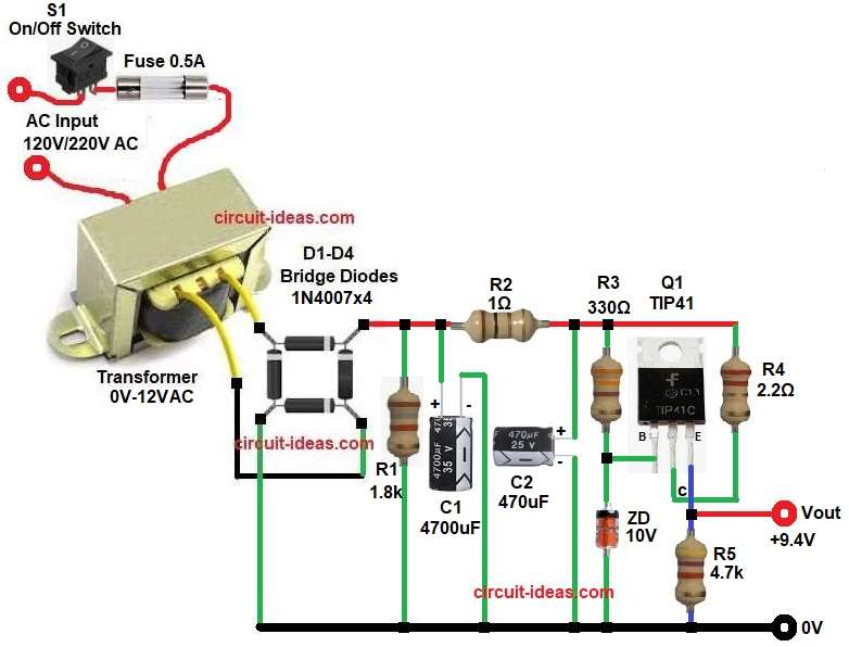
First, AC mains supply given to the transformer and then the transformer steps down 220V AC to 12V AC.
The switch and fuse connected in series with the transformer primary, the switch used to turn the power supply ON and OFF manually and the fuse provides safety protection
Then bridge rectifier D1–D4 converts AC into pulsating DC, after that the large capacitor C1 4700uF filters ripple and so we get unregulated DC.
Now, the DC voltage flows through resistor R2 to the 10V Zener diode, which provides a constant reference voltage to the transistor base and keeps the base voltage stable.
Q1 TIP41 transistor works as series pass transistor and it supplies higher current to load, so output becomes stable.
Emitter of transistor gives output voltage, because emitter voltage is base voltage minus 0.7V the output becomes around 9.3V to 9.4V.
Another capacitor C2 470uF filters remaining ripple, finally we get smooth 9V DC at output.
Formulas with Calculation:
1: Transformer secondary voltage = 12V AC
Peak voltage after rectification:
Vp = Vrms × 1.414
= 12 × 1.414
Vp = 16.97V
Bridge diode drop (approx 1.4V):
DC voltage after rectifier = 16.97 − 1.4
DC voltage = 15.5V
Zener voltage = 10V
Transistor base-emitter drop = 0.7V
Output voltage:
Vout = Vz − Vbe
= 10 − 0.7
Vout = 9.3V
2: Ripple Voltage Formula (Full Wave Rectifier):
Vripple = I / (f × C)
where:
- I is the load current in ampere
- f is the ripple frequency 100Hz for full wave rectifier
- C is the filter capacitor in farads
here,
C1 = 4700uF
Convert into Farads:
C = 4700 / 1,000,000
C = 0.0047 F
Assume load current = 0.5A
Vripple = 0.5 / (100 × 0.0047)
= 0.5 / 0.47
Vripple = 1.06V
So with 1.06V ripple the output becomes smoother and better.
How to Build:
To build a Zener Controlled 9V Regulator Circuit with TIP41 Transistor follow the connection steps below:
- Start, the circuit by collecting all the parts as shown in circuit diagram.
- Then, start with Transformer primary pins connect to AC mains through switch and fuse and secondary 12V wires connect to bridge rectifier AC inputs.
- Next, with bridge rectifier D1–D4 1N4007 connect four diodes in bridge form and two opposite ends connect to transformer secondary.
- Now positive end output goes to filter C1 capacitor and resistor R1 and negative end goes to ground.
- Further, Resistor R2 connect to unregulated DC supply, resistor R3 connect one end from unregulated DC supply and other end to base of transistor Q1 and Zener cathode end and then resistor R4 one end connect to unregulated DC and other end connect to collector of transistor Q1.
- Also, connect resistor R5 one end to the junction of Vout and emitter of Q1 and other end of R5 connect to GND.
- Filter Capacitor C1 2200uF positive pin connect to rectifier positive and negative pin connect to ground.
- Then TIP41 Transistor collector pin connect to unregulated DC supply, base connect through resistor R3 to supply and to Zener diode and emitter goes between regulated output and resistor R5
- Zener Diode 10V cathode connect to transistor base and anode connect to ground.
- Output Capacitor C2 470uF positive connect unregulated DC supply and negative connect to ground.
Conclusion:
To conclude, this Zener Controlled 9V Regulator Circuit with TIP41 Transistor is simple and useful project, as it uses Zener diode for reference voltage and also uses TIP41 transistor for high current output.
Therefore, output voltage becomes stable around 9V.
This circuit is good for small projects, radio circuits and microcontroller boards and in addition, it is easy to build with basic components; so beginners can also make this power supply easily.

Leave a Reply