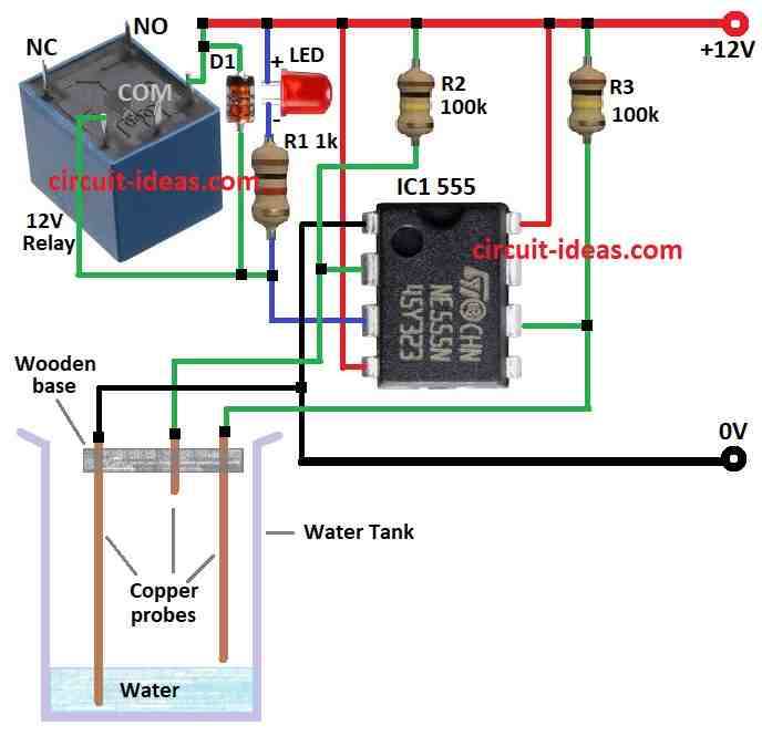
You can build a water level controller for your tank using a cheap and easy circuit with a special chip called a 555.
This circuit will automatically turn off the pump when the tank is full and turn it back on when the water gets too low.
You can even adjust the circuit to match your tank size and how full you want it to get by changing some of the parts.
Circuit Working:
Parts List:
Category | Description | Quantity | Wattage/Specifications |
---|---|---|---|
Resistors | 1k | 1 | 1/4 watt |
100k | 2 | 1/4 watt | |
Semiconductors | IC 555 | 1 | |
LEDs | Any 5mm 20mA | 1 | |
Diode | 1N4148 (D1) | 1 | |
Relay | 12V Relay | 1 | |
Other Components | Water Tank | 1 | |
Copper probes | 3 |
This circuit is an affordable option since it makes use of widely accessible electrical components.
There are few things you need to keep in mind, because of the 100k resistors in our design, pins 2 and 6 sense a voltage even when the water is not hitting the probes.
Neither pin detects a voltage when the probes come into contact with water.
Pins 2 and 6 are just measuring 1/3 and 2/3 of the rail voltage respectively so do not worry about them.
The pins in our circuit can either sense a voltage or none at all.
A LOW is detected by pin 2 and a HIGH by pin 6 , when pin 2 detects a HIGH nothing happens, and when pin 6 detects a LOW, nothing happens.
When the water is LOW, pins 2 and 6 are both HIGH, and the 555s output is LOW.
Pin 3 remains same as the water level increases with the exception that the chip has been prepared via the internal flip flop to change when pin 2 reaches LOW.
Upon reaching pin 2, the water fails to see a HIGH causing the chips output to spike HIGH and the pump to shut off.
Pin 2 experiences a HIGH as the water level drops, but this has no effect on the 555 since pin 2 only affects the LOW.
The chip will change states when the water level drops even lower, because pin 2 is not experiencing a LOW and pin 6 is seeing a HIGH, the output becomes LOW.
Formulas:
We may construct a circuit where the water level sensors (copper probes) control the SET and RESET inputs of the SR latch, which in turn controls the state of a relay for pump or valve control, in order to produce a Water Level Controller circuit utilizing the IC 555 in a Set Reset (SR) latch configuration.
Here is a general formula for same:
Calculating an LED Current Limiting Resistor:
To determine the resistor value RLED for the LED, use the following formula:
RLED = Vsupply − VLED / ILED
where,
- Vsupply is the voltage supply 12V
- VLED is the forward voltage drop of the LED, usually around 2V.
- Desired LED current (20mA in your instance) for ILED .
This simple way of controlling a relay depending on the water level measured by the probes in the tank is made possible by the 555 and SR latch setup.
Depending on particular component qualities and intended operation, adjustments can be required.
How to Build:
To build a Simple Water Level Controller Circuit using IC 555 follow the below mentioned steps for connections:
- Gather all the components as shown in above diagram.
- Connect pin 1 of IC 555 on ground.
- Connect pin 2 to positive supply of 12V through resistor R2.
- Connect pin 3 to positive supply through resistor R1 and LED.
- Connect pin 4 of IC 555 to positive supply of 12V.
- Connect pin 6 of IC 555 to positive supply through resistor R3.
- Connect pin 8 of IC 555 to positive supply of 12V.
- Connect a one pin of relay coil pins through pin 3 and the other pin to a positive supply , and connect the cathode of diode to the positive side of relay and anode to the pin 3 of the relay coil.
- Connect pin 2 of IC 555 to the probe which detects the full tank over flow level, and pin 6 connects to the probe which detect the lower water level, and the ground pin is connected to the copper probe which is suppose to be immersed in water.
Safety Measures:
- As with any do it yourself electrical installation, safety measures are essential both during the circuits construction and operation.
- To prevent electrical risks, make sure you have the required electronics skills and utilize components with the right voltage ratings.
Conclusion:
An DIY method for automatically controlling a tanks water level is to use a 555 IC circuit.
It fills the tank and keeps it from overflowing by controlling a pump using probes and the timers output.
Basic functioning and safety issues are crucial considerations even when they are cost effective.
Leave a Reply