Simple Light to Frequency Converter Circuit using Timer IC 555 changes light brightness into frequency signal, it is useful for light measure, optic sensing and automation.
Also, circuit uses IC 555 timer in astable mode and photodiode to catch light, as more light means more frequency which is easy to see link between light and output.
Circuit Working:
Parts List:
| Components | Values | Quantity |
|---|---|---|
| Capacitor | Ceramic 0.01µF | 1 |
| Semiconductors | Timer IC 555 | 1 |
| Photodiode | 1 | |
| 6V Battery | 1 |
When light hit photodiode it make small photocurrent and IC 555 work in astable mode and capacitor C1 charge and discharge again and again by making pulse signal.
How fast C1 charge depend on photodiode resistance which change with light and more light means more photocurrent and this change charging time so output frequency also changes.
Then pin 3 give square wave and then more light means higher frequency.
Formulas:
Formula for output frequency:
f = 1.44 / (RA + 2RB)C
where:
- f is the frequency in Hz
- RA and RB are the resistors
- C is the capacitor C1
In this circuit:
Photodiode act like resistor with more light means less resistance and less resistance means higher frequency, hence, we can change component values to get different output.
How to Build:
To build a Simple Light to Frequency Converter Circuit using Timer IC 555 follow below steps for connections and assembling:
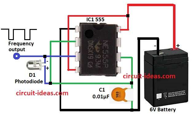
- First, put all parts like in circuit diagram.
- Next, connect 6V battery positive to pin 4 and 8 of IC1.
- Then pin 1 of IC1 goes to GND.
- Now photo diode D1 go between pin 2, pin 3 and GND.
- After that, capacitor C1 go from pin 6 to GND.
- Finally, output signal come from pin 3, it give square wave and frequency change with light.
Conclusion:
To conclude, this article teaches us about Simple Light to Frequency Converter Circuit using Timer IC 555.
More light means more frequency and it is good for light meter, sensor, automation.
Also, this circuit is easy to build and is with stable output and it work with microcontroller or frequency counter.
Leave a Reply