Simple High Power Three Phase Bridge Rectifier Circuit is very important for factory and place where there is need of a big DC voltage and current.
Also, it changes three phase AC voltage to steady DC output which is good for motor, power supply and other uses.
The IC 20L6P45, which functions as a three-phase diode bridge rectifier, is a better choice, as it is small, light, simple and work good with high voltage and current.
Furthermore, this circuit needs good heat sink for extra heat and also this article talk about how it work, build and calculation for three phase full wave rectifier with 20L6P45 module.
Circuit Working:
Parts List:
| Components | Values | Quantity |
|---|---|---|
| Capacitors | Electrolytic 470µF 450V | 4 |
| Semiconductors | IC 20L6P45 | 1 |
| Inductor Coils 100mH / 15 SWG | 2 |
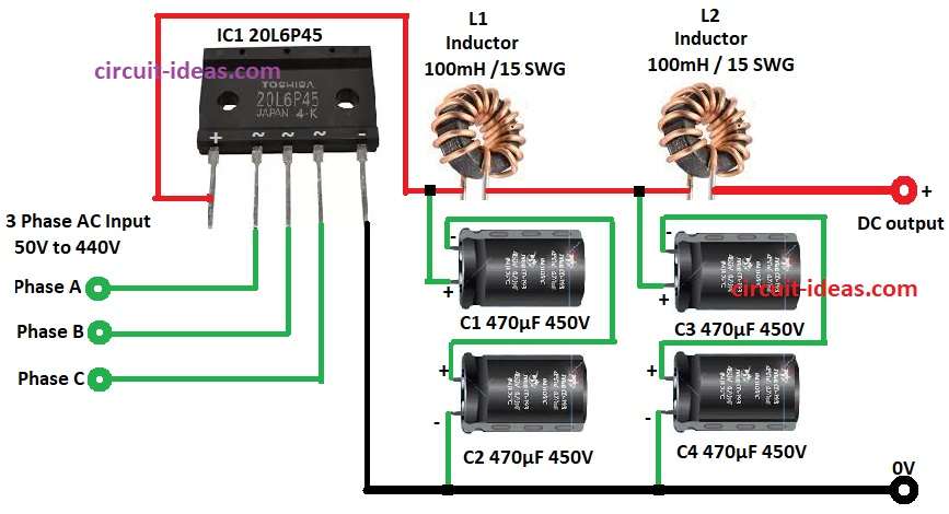
This article show circuit changes three phase AC to DC using special chip 20L6P45 and the three phase are full wave rectifier module; it takes power from three phases like Phase A, B, C and make bumpy DC voltage.
Then to smooth DC voltage it uses capacitors C1, C2, C3, C4 and these capacitors charge and release energy and keep DC steady.
After that, inductor coils L1 and L2 help make output better, less ripple and current flow more smooth.
Moreover, IC 20L6P45 act like three-phase diode bridge and let current flow one way only and this help change AC to DC good.
Formulas with Calculations:
Here simple formulas and calculation for High Power Three Phase Bridge Rectifier Circuit:
DC Output Voltage Vdc = (3 × Vrms) / π
where,
- Vrms is the phase voltage RMS
For 440V system, Vrms = 440 / √3 = 254V
So Vdc = (3 × 254) / π = 243V
Ripple Frequency = 6 × AC supply frequency
For 50Hz AC ripple frequency = 6 × 50 = 300Hz
Capacitor value C = Iload / (fripple × Vripple)
Inductor value L = (Vdc × D) / (ΔI × f)
where,
- D is the duty cycle
- ΔI is the current ripple
- f is the switching frequency
How to Build:
To build a Simple High Power Three Phase Bridge Rectifier Circuit follow the steps mentioned below for connections and assembling:
- First, gather all parts from circuit diagram.
- Next, connect pin 1 of IC1 to join point of capacitor C1 positive and one end of inductor L1.
- After that, connect pin 2 of IC1 to AC input phase A.
- Now connect pin 3 of IC1 to AC input phase B.
- Also, connect pin 4 of IC1 to AC input phase C.
- Then connect pin 5 of IC1 to circuit GND.
- Further, connect inductor L1 between positive of capacitors C1 and C3 and negative of C1 and C3 connect to positive of capacitors C2 and C4 and connect negative of C2 and C4 to GND.
- Finally, connect inductor L2 between positive of capacitor C3 and DC output and connect negative of DC output to GND.
Conclusion:
To conclude, this Simple High Power Three Phase Bridge Rectifier Circuit with 20L6P45 changes AC to steady DC well.
Capacitor filter and inductor smooth help give clean DC output and is good for motor and power supply in factory.
Therefore, right parts choice is important for smooth output voltage and is good working.
Leave a Reply