This project for Arduino LED Dimmer Circuit using IR Remote make simple LED look like smart light.
Here, LED listens to IR remote, IR receiver reads remote signal and then Arduino change LED brightness using PWM.
With Arduino and few parts, we can change brightness sitting on sofa and it feel like small home-automation system; also this project is good for beginners, as it mixes small coding, simple electronics and fun remote tricks.
Arduino Code:
#include <IRremote.h>

int RECV_PIN = 2;
int led = 9;
int brightness = 0;

IRrecv irrecv(RECV_PIN);
decode_results results;

void setup() {
pinMode(led, OUTPUT);
irrecv.enableIRIn();
}

void loop() {
if (irrecv.decode(&results)) {
long value = results.value;

if (value == 0xFFA857) {
  brightness = brightness + 20;
  if (brightness > 255) brightness = 255;
}

if (value == 0xFFE01F) {
  brightness = brightness - 20;
  if (brightness < 0) brightness = 0;
}

analogWrite(led, brightness);
irrecv.resume();


}
}
Circuit Working:
Parts List:
| Components | Values | Quantity |
|---|---|---|
| Resistor | 220Ω 1/4 watt | 1 |
| Semiconductors | Arduino UNO board | 1 |
| White LED | 1 | |
| TSOP4838 IR Receiver | 1 |
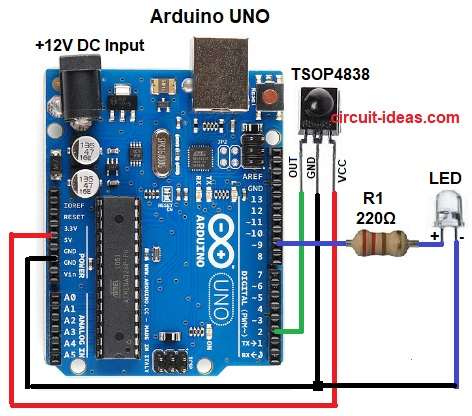
In the above diagram IR receiver takes remote signal and then the signal goes to Arduino digital pin and after that Arduino then decodes it.
When the user presses a button the Arduino increases or decreases LED brightness and LED brightness changes using PWM output pin and then LED becomes bright or dim slowly.
Formula with Calculation:
Below is the LED resistor value formula
R = (Vsource – Vled) / Iled
here,
- Vsource is 5V
- Vled is 2V
- Iled is 0.015A
R = (5 – 2) / 0.015 = 200 ohms approx
So we have used 220 ohm resistor for safety.
How to Build:
To build a Arduino LED Dimmer Circuit using IR Remote follow the below steps:
- First, take all the parts as shown in circuit diagram.
- Next, IR receiver VCC pin goes to Arduino 5V.
- After that, IR receiver GND pin goes to Arduino GND.
- Then IR receiver OUT pin goes to Arduino digital pin 2.
- Also, LED anode (+) goes to Arduino pin 9 through a R1 resistor and finally, LED cathode (-) goes to Arduino GND.
Conclusion:
To conclude, this is a simple Arduino LED Dimmer Circuit using IR Remote, as IR remote makes LED control wireless.
In addition, circuit and code is easy and we can also use same idea for lamps, strips or other small loads.

Leave a Reply