This project is IR Transmitter and Receiver Circuit using 555 and 4017 IC, as it works with infrared light and it also has two parts transmitter and receiver.
Transmitter sends IR signal and receiver catches signal and turns relay ON or OFF and furthermore, it can control small home device without wire.
Circuit Working for IR Transmitter Circuit :
Parts List for IR Transmitter Circuit:
| Components | Values | Quantity |
|---|---|---|
| Resistors | 1k 1/4 watt | 1 |
| 560Ω 1/4 watt | 1 | |
| Capacitors | Ceramic 18nF | 1 |
| Ceramic 33pF | 1 | |
| Ceramic 100nF | 1 | |
| Semiconductors | IC 555 Timer | 1 |
| Standard IR Transmitter LED | 1 | |
| Tactile Push Button Switch | 1 | |
| Power Supply 9V Battery | 1 |
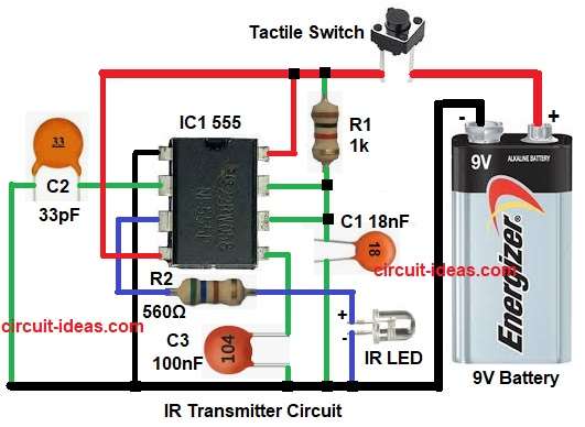
In the above circuit diagram the IC 555 works in a monostable multivibrator mode and in this mode the IC 555 stays OFF normally
When we do not press the switch, output pin 3 stays LOW and when we press the switch, it pulls pin 2 LOW, and the 555 timer wakes up to start timing.
After that, the timing capacitor C1 starts charging through resistor R1 and during this charging time the pin 3 becomes HIGH.
So IR LED glows for that time and after capacitor finishes the charging, voltage on C1 reaches the limit and 555 automatically turns output pin 3 LOW again.
Now IR LED turns OFF and if we press switch again then process repeats and so one press gives one pulse of IR light.
Pulse ON time depends on:
T = 1.1 × R1 × C1
Bigger R1 or bigger C1 gives longer IR ON time.
How to Build IR Transmitter Circuit:
Below is the connection steps for IR Transmitter Circuit:
- First, gather all parts as shown in circuit diagram.
- Next, pin 1 of IC555 goes to ground.
- After that, pin 2 connects to one end of C2 and other end of C2 to ground.
- Also, pin 3 connects to IR LED through R3 and then to ground.
- Then pin 4 and pin 8 go to +9V supply.
- Further, pin 5 connects to one end of C3 and other end to ground.
- Now pin 6 and pin 7 join together and then R1 connects between +9V and pin 6 and 7.
- Next, C1 connects between pin 6 and 7 and ground and finally, switch connects at +9V to send signal only when pressed.
Circuit Working for IR Receiver Circuit:
Parts List for IR Receiver Circuit:
| Components | Values | Quantity |
|---|---|---|
| Resistors | 560Ω 1/4 watt | 1 |
| 10k 1/4 watt | 1 | |
| 1k 1/4 watt | 1 | |
| Semiconductors | IC CD 4017 | 1 |
| Transistor BC547 | 1 | |
| Diode 1N4007 | 1 | |
| Standard IR Receiver LED | 1 | |
| Relay SPST 12V | 1 | |
| Power Supply +12V DC | 1 |
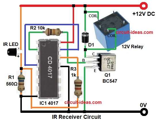
The above circuit diagram is for IR receiver circuit, as it uses IC 4017 decade counter and transistor BC547.
When IR light falls on the photodiode, it produces a small voltage and then signal goes to IC 4017 through R3 and also this IC 4017 counts the input pulses and gives output.
The output drives transistor Q1 and then Q1 transistor operates the relay; moreover, relay switches ON or OFF any external load.
Normally, when there is no IR light then photodiode gives no signal and IC 4017 stays in reset condition.
When IR light comes then input pulse goes to pin 14 of IC 4017 and then IC gives output high on pin 2 and then this output goes to base of Q1 through resistor R2.
Also, Q1 conducts and energizes the relay coil, and finally, the relay contacts connect to the device.
How to Build:
Below is the connection steps for IR Receiver circuit:
- First, gather all parts as shown in circuit.
- Next, pin 2 of IC 4017 goes to base of Q1 through R2.
- After that, pin 4 and pin 15 join together.
- Now pin 8 goes to ground and also pin 13 goes to ground.
- Then pin 14 goes to anode of IR receiver LED and cathode of IR LED goes to +12V.
- Further, pin 16 connects to +12V supply ad then R1 connects between R3 and ground.
- Also, diode D1 connects between relay coil and collector of Q1.
- Finally, collector of Q1 goes to relay coil, other coil end goes to +12V and emitter of Q1 goes to ground.
Conclusion:
To conclude, this project shows easy way to make wireless remote with IR.
Here, transmitter sends small IR pulses and receiver catches pulse and turns relay ON; moreover, we can also control fan, lamp, small gadget, as it is cheap project, easy to make and is good for beginners.

Leave a Reply