This post talks about Building an Auto Street Light Circuit using IC 741 and Transistor.
It turns ON at night and OFF at day.
This circuit is simple and saves energy.
It uses relay to control light, LDR to sense light, BC547 transistor drives relay and IC 741 works as a comparator.
It is an easy to make, cheap and is good for small uses or for learning.
Circuit Working:
Parts List:
| Component | Specification | Quantity |
|---|---|---|
| Resistors (All resistors are 1/4 watt unless specified) | ||
| 100k | 2 | |
| 1k | 2 | |
| 10k | 1 | |
| 470Ω | 1 | |
| LDR Light Dependent Resistor | 1 | |
| Preset 10k | 1 | |
| Semiconductors | ||
| IC LM741 Operational Amplifier | 1 | |
| Transistor NPN BC547 | 1 | |
| Diode 1N4001 | 1 | |
| Relay 12V SPDT | 1 |
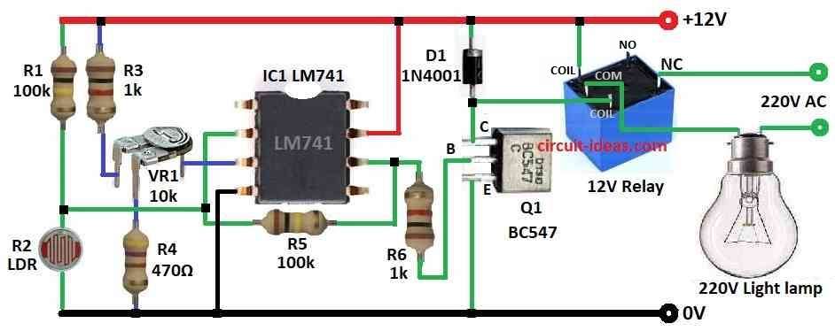
Auto street light circuit turns bulb ON at night and OFF at day.
LDR is used as light/dark sensor.
R1 and LDR make voltage divider.
VR1 preset sets sensitivity to IC 741s non-inverting input (+).
At day time the LDR resistance is low with more voltage to inverting input (–).
At night time the LDR resistance is high with less voltage to inverting input (–).
IC 741 compares both inputs.
If (–) input > (+) then output is LOW.
If (–) input < (+) then output is HIGH.
HIGH output turns ON BC547 transistor and relay gets power with street light turns ON.
When light increases the LDR resistance drops with (–) input and voltage rises with output LOW.
Transistor is OFF with relay OFF and street light gets OFF.
Formulas and Calculations:
Formulas for Auto Street Light Circuit:
1. Voltage at LDR (Divider Rule):
V_LDR = (R_LDR / (R_LDR + R1)) × Vcc
where,
- R_LDR is the LDR resistance
- R1 is the fixed resistor for 100k
- Vcc is the 12V power
2. Reference Voltage at (+) of IC741:
V_ref = (RV1 / (RV1 + R3)) × Vcc
where,
- RV1 is the variable resistor for 10k
- R3 is the fixed resistor for stable input
- Vcc is the 12V supply
3. Base Current of Transistor BC547:
I_B = (V_out – V_BE) / R6
where,
- V_out is the output from IC 741 which is around 12V when HIGH
- V_BE is the 0.7V for base-emitter voltage
- R6 is the base resistor for 1k
Example: If V_out = 12V:
I_B = (12 – 0.7) / 1k = 11.3 mA
4. Relay (Collector) Current:
I_C = β × I_B
where,
- β is the transistor gain between 100 to 200
- I_B is the base current
Example:
If I_B = 11.3 mA, β = 100:
I_C = 100 × 11.3 mA = 1.13 A
5. Power in Resistor:
P = I² × R
where,
- I is the current in resistor
- R is the resistor value
How to Build:
To build an Auto Street Light Circuit using IC 741 and Transistor follow the below mentioned steps for connections:
- Take all parts as in circuit diagram.
- Connect pin 2 of IC 741 to pin 6 using resistor R5.
- Connect R1 between +12V and pin 2.
- Connect LDR between pin 2 and GND.
- Connect pin 3 of IC to center leg of VR1.
- Connect 2nd leg of VR1 to +12V through R3 and 3rd leg to GND through R4.
- Connect pin 4 of IC to GND.
- Connect pin 6 of IC to base of Q1 BC547 using resistor R6.
- Connect pin 7 of IC to +12V power.
- Connect collector of Q1 to one side of relay and other side of relay to +12V.
- Connect emitter of Q1 to GND.
- Connect diode D1 cathode to +12V and anode to collector of Q1.
- Connect 220V AC bulb and 220V supply in series between NC and Common pins of relay.
Conclusion:
This Building an Auto Street Light Circuit using IC 741 and Transistor is easy to make.
It saves power, uses few parts and works well.
The circuit is good for street, garden or outdoor lights.
Light level can be adjusted using VR1.
References:
Design And Fabrication Of Automatic Street Light Control System