• Skip to primary navigation
  • Skip to main content
  • Skip to primary sidebar

Circuit Ideas for You

Get free circuit ideas online.

  • Home
  • Privacy Policy
  • About
Home » Christmas Music Box Circuit using IC UM66

Christmas Music Box Circuit using IC UM66

Last updated on 15 November 2025 by Admin-Lavi Leave a Comment

This is fun project for small Christmas Music Box Circuit using IC UM66.

UM66 chip already has melody inside.

When power ON, it plays Christmas notes.

It is good for greeting cards, toys and mini gifts.

Circuit Working:

Christmas Music Box Circuit Diagram using IC UM66

Parts List:

Part NameValueQuantity
Resistor4.7k 1/4 watt1
Capacitor Electrolytic 1uF 25V1
SemiconductorsIC UM661
Transistor BC5471
Speaker 4 to 8 ohms1
Battery 3V1

Main brain of this circuit is IC UM66.

UM66 makes melody when power is ON.

Its output is weak, so transistor makes it strong.

Transistor drives the small speaker.

Resistor controls base current.

Capacitor keeps supply smooth.

Speaker plays the Christmas tune.

Below is the list of Christmas melodies commonly found in UM66T-XX series melody ICs.

UM66T19 – Jingle Bells
UM66T20 – We Wish You a Merry Christmas
UM66T21 – Silent Night
UM66T22 – Santa Claus Is Coming to Town
UM66T23 – Joy to the World
UM66T24 – O Christmas Tree
UM66T25 – Rudolph the Red-Nosed Reindeer
UM66T26 – Little Town of Bethlehem
UM66T27 – O Come All Ye Faithful
UM66T28 – The First Noel

Note:

Different manufacturers sometimes use slightly different tune numbers.

But the above list is the most widely used set for Christmas UM66T series.

How to Build:

Below are the steps to build a Christmas Music Box Circuit using IC UM66:

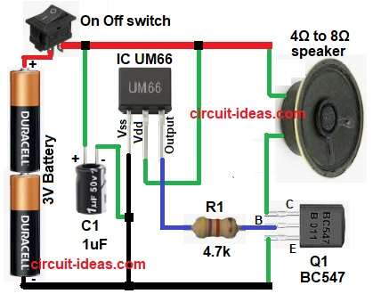
  • Collect all parts shown in circuit above.
  • Pin 3 goes to transistor base through resistor R1.
  • Pin 2 of UM66 goes to 3V positive.
  • Pin 1 goes to ground.
  • Emitter of transistor goes to ground.
  • Speaker one side goes to transistor collector.
  • Other side of speaker goes to positive.
  • C1 capacitor goes between positive and ground.
  • Add switch in battery line for ON and OFF.

References:

Datasheet IC UM66

Filed Under: Audio Circuits

About Admin-Lavi

Lavi is a B.Tech electronics engineer with a passion for designing new electronic circuits. Do you have questions regarding the circuit diagrams presented on this blog? Feel free to comment and solve your queries with quick replies

Previous Post: « Jingle Bell Song Circuit with Arduino and Piezo Buzzer
Next Post: DIY Arduino Based Weather Station Circuit »

Reader Interactions

Leave a Reply Cancel reply

Your email address will not be published. Required fields are marked *

Primary Sidebar


Categories

  • Alarm Circuits (45)
  • Amplifier Circuits (67)
  • Arduino Projects (99)
  • Audio Circuits (114)
  • Automobile Circuits (19)
  • Battery Charger Circuits (65)
  • Free Energy (13)
  • Heater and Temperature Controllers (13)
  • High Voltage (1)
  • Indicator Circuits (45)
  • Inverter Circuits (20)
  • IoT projects (1)
  • LDR Circuits (26)
  • LED and Lamps (148)
  • Meters and Testers (30)
  • Motor Controllers (22)
  • Oscillator Circuits (39)
  • Power Supply Circuits (104)
  • Remote Control Circuits (10)
  • Security and Protection (29)
  • Sensors and Detectors (126)
  • Solar Circuits (29)
  • Timer Circuits (41)
  • Transistor Circuits (87)
  • Transmitter Circuit (17)
  • Tutorials (8)
  • Water Level Controller (6)

Recent Posts

  • 12V Battery Low Voltage Alarm Circuit
  • Low Voltage Alert Circuit for 9V Battery
  • Digital Code Lock Circuit using IC 4017
  • Darkness Activated LED Circuit
  • Fan Start 10 Second Delay Timer Circuit

Recent Comments

  1. TDHofstetter on DIY Variable Power Supply Circuit using Arduino
  2. feathbuff on Simple Micro Ampere Meter Circuit
  3. Admin-Lavi on Simple School Project Multimeter Circuit
  4. choke on Simple School Project Multimeter Circuit
  5. Admin-Lavi on Analog to Digital Converter Circuit using IC 555

Copyright © 2026 | New Circuit Ideas