This DIY Arduino Based Weather Station Circuit is very easy project, as it uses Arduino Uno, DHT11 sensor, 16×2 LCD and one potentiometer.
Here, the LCD show temperature and humidity on screen and potentiometer controls LCD contrast and brightness;
The wiring is simple and code are very easy and anyone can build this circuit at home.
Arduino Code:
#include <LiquidCrystal.h>
#include <DHT.h>

#define DHTPIN 2
#define DHTTYPE DHT11

DHT dht(DHTPIN, DHTTYPE);

LiquidCrystal lcd(7, 6, 5, 4, 3, 8);

void setup() {
lcd.begin(16, 2);
dht.begin();
}

void loop() {
float h = dht.readHumidity();
float t = dht.readTemperature();

lcd.clear();
lcd.setCursor(0, 0);
lcd.print("Temp: ");
lcd.print(t);
lcd.print(" C");

lcd.setCursor(0, 1);
lcd.print("Hum: ");
lcd.print(h);
lcd.print(" %");

delay(2000);
}
Code Explanation:
- The code loads LCD and DHT libraries.
- DHT object reads humidity and temperature.
- LCD begins with 16 columns and 2 rows.
- In loop Arduino reads humidity inside variable h.
- Arduino reads temperature inside t.
- LCD clears old values.
- LCD prints new values.
- Delay gives 2 second gap for stable display.
Circuit Working:
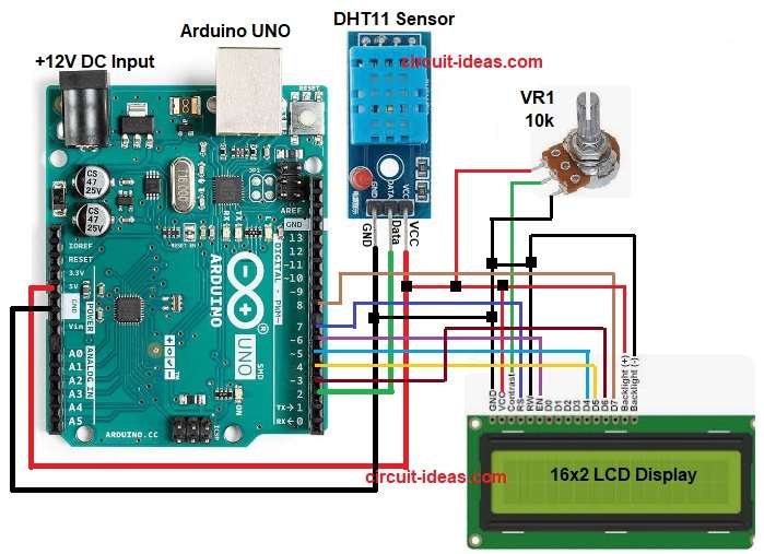
Parts List:
| Components | Quantity |
|---|---|
| Potentiometer 10k | 1 |
| Arduino UNO | 1 |
| DHT11 Sensor | 1 |
| 16×2 LCD Display | 1 |
| USB Cable for Arduino | 1 |
The Arduino weather station uses DHT11 sensor to read air temperature and humidity; also this sensor read temperature from 0 to 50 degree C with about plus minus 2 degree error.
Humidity it read from 20 to 80 percent with about plus minus 5 percent error; also the sensor take one reading every 1 second and it send data after each 1 second gap.
Power the sensor from Arduino 5V and GND and then connect data pin to Arduino digital pin, after that potentiometer adjusts screen clarity
Also, use 4.7k to 10k pull-up on data line if module not have it and do not read faster than one read per second.
Wait 1 to 2 seconds between reads and for better accuracy use DHT22 instead of DHT11.
How to Build:
To build a DIY Arduino Based Weather Station Circuit follow the below steps for connections:
- First, assemble all the parts as shown in circuit diagram.
- Next, DHT11 sensor VCC pin connect to Arduino 5V and DHT11 sensor GND pin connect to Arduino GND DHT11 sensor Data pin connect to Arduino digital pin 2.
- Now LCD pin 1 GND connect to Arduino GND, LCD pin 2 VCC connect to Arduino 5V and LCD pin 3 connect to center pin of potentiometer and potentiometer side pin goes to 5V and other side to GND.
- After that, LCD pin 4 RS connect to Arduino pin 7, LCD pin 5 RW connect to GND and LCD pin 6 EN connect to Arduino pin 6.
- Then LCD pin 11 D4 connect to Arduino pin 5, LCD pin 12 D5 connect to Arduino pin 4 and LCD pin 13 D6 connect to Arduino pin 3.
- Finally, LCD pin 14 D7 connect to Arduino pin 8 and LCD pins 15 and 16 connect to 5V and GND for backlight.
Conclusion:
To conclude, this DIY Arduino Based Weather Station Circuit is simple and useful project as it gives basic real time weather data.
Furthermore, the circuit is easy for students and hobby makers and we can upgrade with more sensors later;
Also, we can add IoT or data logging, as its a great small step into Arduino world.

Leave a Reply