LED lights last long and use less power so more people like them now.
Furthermore, this article for Designing a Simple 7W LED Bulb Circuit shows how to make and use a 7W LED bulb circuit.
Also, parts needed for this circuit are 230V AC power, MOV, capacitors, resistors, bridge rectifiers, Zener diodes.
So, be careful! this circuit uses 230V AC and always follow safety rules.
Circuit Working:
Parts List:
| Components | Values | Quantity |
|---|---|---|
| Resistors | 330k 1/4 watt | 1 |
| 10Ω / 2W | 1 | |
| 10Ω / 5W | 1 | |
| MOV 7D471K | 1 | |
| Capacitors | Electrolytic 1µF / 400V | 1 |
| 100µF / 50V | 1 | |
| Semiconductors | Bridge Rectifier Module 1N4007 | 4 |
| Zener Diode 16V / 1W | 1 | |
| 1 Watt 8mm white LEDs | 7 |
Remember! handle this circuit very carefully as it runs on high 230V AC.
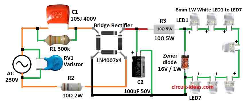
First, 230V AC connects to the MOV and then MOV protects from voltage spikes.
Then resistor R1 and capacitor C1 lowers the voltage and current, next, this goes to the bridge rectifier which changes AC to pulsing DC.
Then this DC is not smooth so it needs filtering.
So varistor VR1 also helps protect from high voltage surges and capacitor C2 filters the DC and Zener diode controls the voltage.
After that, we connect 1W white LEDs or bright 8mm white LEDs in series after the Zener diode.
Finally, we can also change the number of LEDs as needed and be sure to connect LED anode and cathode in correct direction.
Formulas:
To make a simple 7W LED bulb circuit we must choose the right parts using some basic formulas.
C1 AC Capacitor:
Used to control current.
Formula for reactance:
XC = 1 / (2πfC1)
where,
- f is 50 or 60Hz
Current:
I = Vac / XC
Choose C1 to set correct current for rectifier.
R2 Current Limiting Resistor:
Use Ohms Law:
R2 = Vac / Idesired
where,
- Idesired is the current we want in circuit
C2 Filter Capacitor:
Reduces ripple in DC.
C2 = ILED / (f × Vripple)
where,
- f is 2 × AC frequency for full-wave
- ILED is LED current
R3 Zener Diode Resistor:
Controls current to Zener diode.
R3 = (VZener − VLED) / IZener
where,
- IZener is around 10 to 20mA
- LEDs in Series for 7 LEDs:
Total voltage:
Vtotal = 7 × VLED
- VLED is 2.1V
- Vtotal is 14.7V
R1 Discharge Resistor for C1:
Helps safely drain capacitor C1.
τ = R1 × C1
Important:
Always check part ratings and take care as this circuit runs on high 230V AC and hence, always follow safety first and also this information helps us build a working 7W LED bulb circuit.
How to Build:
Designing a Simple 7W LED Bulb Circuit following are the steps to follow for connections:
- First, put all parts same as in the circuit diagram.
- Next, connect Varistor RV1 across 230V AC input.
- Then one AC pin of bridge rectifier goes to AC input through capacitor C1 and other AC pin of bridge goes to other AC input through resistor R2.
- Now connect filter capacitor C2 across (+) and (–) of bridge rectifier.
- After that, connect cathode of Zener diode to (+) of rectifier using resistor R3 and connect anode of Zener to (–) of bridge rectifier.
- Further, connect LED string 7 LEDs in series of positive side to where R3 and Zener meet and then connect negative LED side to ground (GND).
- Finally, put resistor R1 parallel to capacitor C1.
Safety Tips:
- Use box and wires with good insulation to avoid shock and use parts rated more than 230V for safe use.
- Always ground the system properly.
- Use resistors to limit current and stop overheating and fire.
- Zener diode helps protect LEDs from high voltage.
- Put warning signs to alert about high voltage.
- Also, always follow safety rules and local electrical codes.
Conclusion:
To conclude, this Designing a Simple 7W LED Bulb Circuit is simple and saves power, with MOV, Zener, filter and current limit parts circuit works well and protects parts.
Moreover, it shows how LED is useful and efficient for modern lighting and so always focus on safety when working with high voltage.
Leave a Reply