The Digital Display AC Line Tester Circuit is a compact electronic device that detects the presence of mains AC voltage without direct contact, it operates wirelessly, making it a safe and convenient mains voltage tester.
When the sensing probe comes near a live AC wire then the circuit detects the field and shows the count on a 7-segment display.
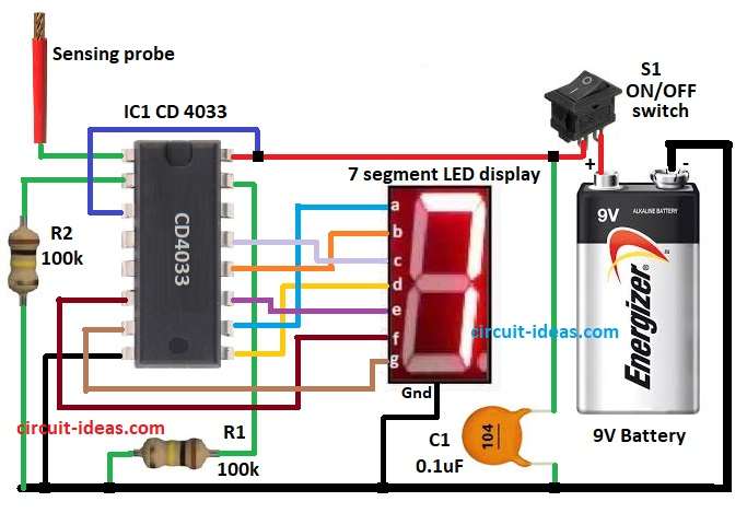
The main IC used here is CD 4033 which is a Johnson decade counter and display driver and it directly drives a 7 segment display without needing a decoder.
Circuit Working:
Parts List:
| Components | Values | Quantity |
|---|---|---|
| Resistors | 100k 1/4 watt | 2 |
| Capacitor | Ceramic 0.1uF | 1 |
| Semiconductors | IC CD 4033 | 1 |
| 7-Segment LED Display Common Cathode | 1 | |
| ON/OFF Switch | 1 | |
| Battery 9V PP3 | 1 | |
| Sensor Probe 10cm insulated wire | 1 |
To begin with, the sensing probe acts like an antenna and when the probe comes close to a live AC wire it picks up the AC electric field.
This signal is very weak but enough to provide small triggering pulses to pin 1 of the CD 4033 IC; then the CD 4033 IC advances its counter each time it receives a pulse at pin 1.
The circuit decodes the output internally and displays it on the 7-segment display.
When no voltage detected, the display remains steady and when the probe detects mains voltage, the counter increments and the 7-segment display shows a digit.
In this way the tester confirms the presence of mains voltage wirelessly.
Note:
CD 4033 IC advances by one digit for each input pulse the formula for display count is just simple:
Count displayed = Number of pulses sensed by pin 1
How to Build:
To build a Digital Display AC Line Tester Circuit follow the below steps for connections:
- First, gather all the parts as shown in above circuit diagram
Connection of CD4033 IC:
- Next, pin 1 goes to sensing probe as it catch weak AC signal.
- Pin 2 goes to ground with resistor R2 so clock not stop.
- Pin 3 goes to Vcc so display work normal.
- Pin 8 goes to battery negative GND.
- Pin 15 goes to ground with resistor R1 so counter does not reset by itself.
- Lastly, pin 16 goes to +9V battery positive.
Connection of 7 segment LED display:
- Pin 6 goes to segment f.
- Pin 7 goes to segment g.
- Pin 9 goes to segment d.
- Pin 10 goes to segment a.
- Pin 11 goes to segment e.
- Pin 12 goes to segment b.
- Pin 13 goes to segment c.
- Pin GND of segment connect to the GND
- Then capacitor C1 connect between pin 16, pin 3 and switch side other end of C1 goes to ground.
- Finally, switch S1 connect between capacitor and +9V battery as it turn circuit ON or OFF.
Conclusion:
To conclude, the Digital Display AC Line Tester Circuit is a very simple and low-cost project that detects mains voltage wirelessly; also it is safe because it does not require a direct connection to the AC mains.
The sensing probe only picks up the electric field and then the CD 4033 IC makes it easy to directly drive the 7 segment display.
Hence, this project is useful for electricians, students and hobbyists to check live AC wires without risk.