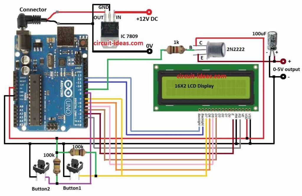
This DIY Variable Power Supply Circuit using Arduino makes changeable power.
It uses transistor and resistors to change 9V output from IC 7809 regulator.
One 100uF capacitor help clean the output voltage.
Two pushbuttons can change the voltage by hand.
LCD screen show real output voltage.
Coding:
#include <LiquidCrystal.h>

LiquidCrystal lcd(12, 11, 5, 4, 3, 2);

int button1 = 7;
int button2 = 8;
int pwmPin = 9;

int dutyCycle = 0;

void setup() {
  lcd.begin(16, 2);
  lcd.print("Variable Power Supply");
  pinMode(button1, INPUT);
  pinMode(button2, INPUT);
  pinMode(pwmPin, OUTPUT);
}

void loop() {
  if (digitalRead(button1) == HIGH) {
    dutyCycle++;
    if (dutyCycle > 255) {
      dutyCycle = 255;
    }
  } else if (digitalRead(button2) == HIGH) {
    dutyCycle--;
    if (dutyCycle < 0) {
      dutyCycle = 0;
    }
  }

  analogWrite(pwmPin, dutyCycle);

  lcd.setCursor(0, 1);
  lcd.print("Voltage: ");
  lcd.print(dutyCycle * 9 / 255);
  lcd.print("V");
  delay(100);
}
Code Explanation:
- Include Liquid Crystal library to control LCD.
- In setup, print welcome, start LCD and set input/output pins.
- In loop check push buttons always.
- If button 1 is pressed duty cycle goes up.
- If button 2 is pressed then duty cycle goes down.
- Duty cycle change PWM output and so voltage also changes.
- LCD will show voltage at that time.
Circuit Working:
Parts List:
| Component | Quantity |
|---|---|
| Resistors | |
| 1k 1/4 watt | 1 |
| 100k 1/4 watt | 2 |
| Capacitor | |
| 100µF 25V | 1 |
| Semiconductors | |
| Arduino Uno Board | 1 |
| LCD 16X2 | 1 |
| IC 7809 | 1 |
| Tactile switches | 2 |
| Transistor 2N2222 | 1 |
Arduino Uno give power to this variable power supply circuit.
IC 7809 give fixed 9V output if input is more than 9V then it does not changes.
Voltage divider bring down voltage to 0 to 5V so Arduino can read it.
Pin 9 of Arduino send PWM signal.
PWM drive transistor like a switch.
Arduino read the small voltage and show it on LCD.
Arduino uses voltage divider calculation to find real output voltage.
1k resistor control transistor base current so it control how much it work.
100µF capacitor connect between 0 to 5V output and ground to make voltage stable and clean.
Capacitor also reduces the noise.
LCD show the voltage at that time.
How to Build:
To build a DIY Variable Power Supply Circuit using Arduino follow the below mentioned steps for connections:
- Collect all parts like in circuit diagram.
- Connect IC 7809 to give fixed 9V DC to Arduino.
- Connect button1 with one leg to pin 7 and other leg to ground.
- Connect button2 with one leg to pin 8 and other leg to ground.
- Put 100k resistor between pin 7 and 5V on Arduino.
- Put another 100k resistor between pin 8 and 5V on Arduino.
- Connect LCD R/W pin to ground of Arduino.
Connect 2N2222 transistor:
- Collector goes to 5V power
- Base goes to pin 9 through 1k resistor
- Emitter goes to 0 to 5V output.
Connect 100µF capacitor:
- Positive leg goes to 0 to 5V output
- Negative leg goes to ground from negative of output.
LCD Connections to Arduino Uno Board:
| Arduino Pin | LCD Pin | Function |
|---|---|---|
| 2 | RS | Register Select |
| 3 | EN | Enable |
| 4 | D4 | Data Bit 4 |
| 5 | D5 | Data Bit 5 |
| 6 | D6 | Data Bit 6 |
| 7 | D7 | Data Bit 7 |
| 11 | Backlight+ | Positive supply for backlight |
| 12 | Backlight- | Negative supply for backlight |
| 5V | VCC | Positive supply for LCD |
| GND | GND | Ground for LCD |
Conclusion:
This project for DIY Variable Power Supply Circuit using Arduino show how make simple and easy variable power source.
PWM duty cycle changes so output voltage also change in a set range.
LCD give feedback to check output voltage.
Project can be made better by adding auto voltage control or more accurate voltage reading.