A dual limit comparator is an important electronic circuit which compares one input voltage with two fixed voltage levels.
In simple words, this Dual Threshold Voltage Comparator Circuit using IC LM741 checks whether the input voltage stays within a fixed range and it also checks whether the voltage crosses the upper limit or the lower limit.
Because of this action, many engineers also call it a window comparator.
In this circuit, the LM741 operational amplifier works as the main comparator and along with this, resistors and 1N4148 diodes create two reference voltage limits.
Therefore, when the input signal crosses the set range the output changes immediately and as a result, this circuit is useful for over-voltage protection, battery monitoring, signal level detection and alarm systems.
Circuit Working:
Parts List:
| Components | Values | Quantity |
|---|---|---|
| Resistors | 15k 1/4 watt | 1 |
| 33k 1/4 watt | 2 | |
| Semiconductors | IC LM741 | 1 |
| Diode 1N4148 | 4 | |
| Power Supply +15V and -15V | – |
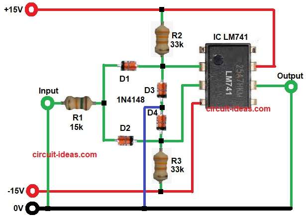
At start, the input signal enters the circuit through resistor R1 which then goes to diode network made by D1 and D2.
Meanwhile, resistors R2 and R3 make a voltage divider network, since both resistors have same value the divider gives a balanced reference point.
Next, diodes D3 and D4 make two separate threshold levels then the circuit compares the input voltage with these two limits.
When the input voltage stays between the upper and lower limits the output stays in normal state.
However, when the input voltage goes above the upper limit the LM741 IC output quickly changes to one saturation level.
Similarly, when the input voltage goes below the lower limit the output changes to the opposite saturation level.
So this circuit works like a voltage window detector, if the signal stays inside the window the output remains stable and if it moves outside then the output changes.
How to Build:
To build a Dual Threshold Voltage Comparator Circuit using IC LM741 following steps are required for connection:
- Circuit start by collecting all the parts as in diagram above.
- Next, start with pin 2 Inverting input (-) which connects to junction of resistor R2 and diodes D1 and D3.
- Then take pin 3 of IC Non-inverting input (+) and connect junction of resistor R3 and diodes D2 and D4.
- Then pin 6 of IC is the output pin and connect at output end and ground.
- Pin 7 of IC is the +VCC pin and connect to +15V.
- Connect pin 4 V- of IC to -15V of IC.
- Connect resistor R1 one end between diodes D1 and D2 and other end connect to input and input end connect to ground.
Conclusion:
The Dual Threshold Voltage Comparator Circuit using IC LM741 is a simple and useful voltage monitoring circuit which checks whether the input voltage stays within a fixed voltage window.
Moreover, the diode network creates accurate upper and lower limits and therefore, this circuit becomes highly suitable for protection and sensing applications.
In addition, its simple design which makes it easy to build, test and use in practical electronic projects.