An LDR changes its resistance when light falls on it and alight detector circuit uses this property in a Wheatstone bridge.
One side of the bridge contains the LDR and a fixed resistor connected in series, while the other side contains a potentiometer and another fixed resistor connected in series.
Furthermore, the circuit applies a voltage across two opposite corners of the bridge and takes the output voltage from the other two corners.
Op-amp can make small output voltage bigger and this bigger voltage can turn ON the LED and when light hits the LDR the output voltage goes down and LED turns ON.
Circuit Working:
Parts List:
| Components | Values | Quantity |
|---|---|---|
| Resistors | 10k 1/4 watt | 3 |
| 330Ω 1/4 watt | 1 | |
| Potentiometer 10k | 1 | |
| LDR | LDR | 1 |
| Semiconductors | IC LM741 | 1 |
| Transistor BC547 | 1 | |
| LED red 5mm 20mA | 1 | |
| 9V Battery | 1 |
Our light detector circuit works like a balance scale, but it uses light instead of weight.
The circuit has two sides: one side contains the LDR (the light sensor) and an adjustable resistor (the potentiometer), while the other side contains two identical 10 kΩ fixed resistors.
In dark LDR act like heavy weight means in high resistance and tilt the scale and when light come LDR get lighter with low resistance and balances the scale.
Also, special chip called op-amp act like referee and it watches voltage at point C and point D.
In the dark, the LDR side (point C) has a higher voltage and the op-amp detects the imbalance and wen light hits the LDR, points C and D reach similar voltages and the bridge becomes balanced.
Moreover, op-amp uses this information to control small switch like transistor.
If dark voltage is high on LDR side and op-amp turns ON the switch and LED turns ON and if bright voltages is equal and op-amp turns OFF the switch and LED turns OFF.
Finally, in simple words the LED turns ON in dark and turns OFF in light and it also work by LDR reacting to light.
What is Wheatstone Bridge and its formula:
A Wheatstone bridge measures an unknown resistance.
It has two legs, and one leg contains the unknown resistor and when the two legs balance and no current flows through the middle branch, we can calculate the unknown resistance.
Also, it gives more accurate result than normal voltage divider and it work like old-style potentiometer.

Formula:
It is important to understand balance in Wheatstone bridge same voltage at point C and D and balance happen when:
R1 / R2 = R3 / R4
This means the ratio of R1 to R2 equals the ratio of R3 to R4 and when the bridge balances, points C and D reach the same voltage, so no current flows between them.
How to Build:
To build a Light Detector Circuit using Wheatstone Bridge below mentioned are the steps for connections:
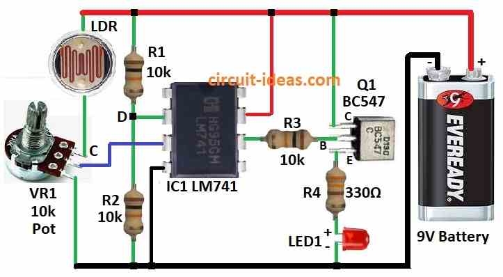
- First, put all parts like shown in circuit diagram.
- Next, connect pin 2 of IC1 LM741 op-amp to middle of R1 and R2.
- After that, connect pin 3 of IC1 to center pin of VR1 potentiometer.
- Now connect pin 4 of IC1 to ground.
- Then connect pin 6 of IC1 to base of transistor Q1.
- Also, connect pin 7 of IC1 to +9V battery.
- Join top leg of VR1 to +9V through LDR, connect center leg of VR1 to pin 3 of IC1 and then connect bottom leg of VR1 to ground.
- Lastly, Q1 collector goes to +9V, base goes to pin 6 of IC1 through resistor R3 and then emitter goes to ground through resistor R4 and LED1.
Safety Tips:
- Op-amps are sensitive to static and touch metal to ground, before touching them, also thy get hot so if needed use heat sink to cool.
- Always double check the wiring as wrong connection can damage the parts and follow diagram and connect carefully.
- Be safe while making and testing circuit.
Conclusion:
Light Detector Circuit works like balance scale using Wheatstone bridge, during dark LDR acts like heavy weight and tilts balance and turns ON the LED and during light the balance is even and LED turns OFF.
Also, op-amp works like referee and checks balance and controls the LED.
So always put safety first and use correct tools, safe power and work on non-metal surface and also have fun making our own light detector!
Leave a Reply