One way to give steady current to laser diode is using a Simple Laser Diode Driver Circuit using IC LM317; as laser diode are very sensitive to current and with wrong current can damage it.
Furthermore, LM317 usually gives voltage but here it gives constant current instead.
Circuit Working:
Parts List:
| Components | Values | Quantity |
|---|---|---|
| Resistors | 330Ω 1/4 watt | 1 |
| Potentiometer 10k | 1 | |
| Capacitors | Ceramic 0.1μF | 1 |
| Electrolytic 1μF 25V | 1 | |
| Semiconductors | IC LM317 | 1 |
| Laser diode 650nm 5mW | 1 | |
| 9V Battery | 1 |
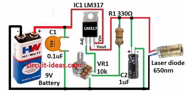
To begin with, this article show simple way to drive laser diode using LM317 IC.
First, the battery power goes to 0.1uF ceramic capacitor and this capacitor remove noise and work like high frequency filter and then it cleans DC and goes to pin 3 Vin of LM317 IC.
Pin 1 (Adj) connect to ground through 10k potentiometer and fixed resistor of voltage divider, hence, adjusting potentiometer change voltage at pin 1 and control output current; also this setup set limit for laser diode current.
Then pin 2 (Vout) is where current come out from LM317 and 1uF capacitor at output help remove leftover oscillation and act like bypass and reduces ripple and spikes.
Therefore, by changing potentiometer, changes reference voltage at pin 1, changes output current and control laser light brightness.
IC LM317 Current Limit Circuit and Formula:
For more safety to laser diode we can add extra LM317 current limit circuit like in diagram below.
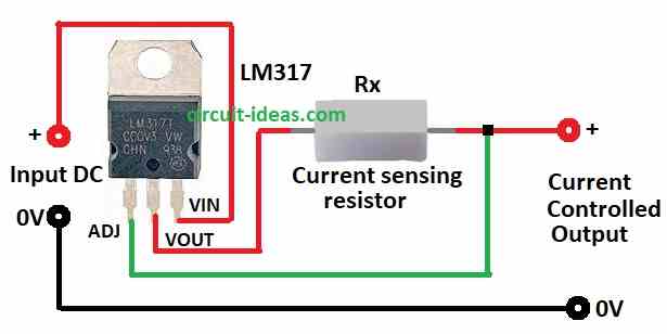
Formula to find current limit resistor (Rx):
Rx = (Vref – 1.25V) / Ilaser
where:
- Rx is the resistor value in ohms Ω
- Vref the voltage at ADJ pin set by voltage divider
- 1.25V is the LM317 inside reference voltage
- Ilaser is the laser diode working current in amps A
How to Build:
To build a Simple Laser Diode Driver Circuit using IC LM317 follow the below mentioned steps:
- First, collect all parts as shown in circuit diagram.
- After that, connect pin 1 (Adj) of LM317 to top leg of VR1 pot.
- Next, connect pin 2 (Vout) to positive of laser diode, other diode leg to ground.
- Then connect R1 resistor from Vout (positive) to middle leg of VR1 pot.
- Now connect pin 3 (Vin) of LM317 to +9V battery through C1 capacitor and connect to ground, also connect C2 capacitor from Vout pin to ground.
Safety Tips:
- Always wear laser safety glasses designed for our lasers wavelength and with the correct OD rating, as the OD rating indicates how much laser light the glasses block.
- Never look at laser beam or reflection and even for short time, because even low power laser can harm eyes if not careful.
- Follow safety steps to avoid danger.
Conclusion:
To conclude, this Simple Laser Diode Driver Circuit using IC LM317 gives steady current to laser diode and controlled current is important for laser long life and safe work.
As a result, if we are new to lasers then ask help from someone who knows electronics and laser safety.
Leave a Reply