First, every electronic project start small, but sometimes current is not enough, so many circuits work fine at 500mA, however real loads like motors, leds and power modules need more current, so instead of redesign full system, we can just boost current using a smart add-on circuit.
Next, this External Current Booster Circuit using Transistor and MOSFET gives simple and strong solution, as it takes low current signal and then converts it into high current output up to 4A, also it keeps control simple while handling heavy load in efficient way.
Moreover, this circuit uses common parts like transistors, Mosfet, inductor and diode, therefore, it is easy to build and also easy to modify and also in addition, it improves performance without making circuit too complex.
Finally, if we want reliable way to increase current without changing main design, then this circuit is very good and perfect choice.
Circuit Working:
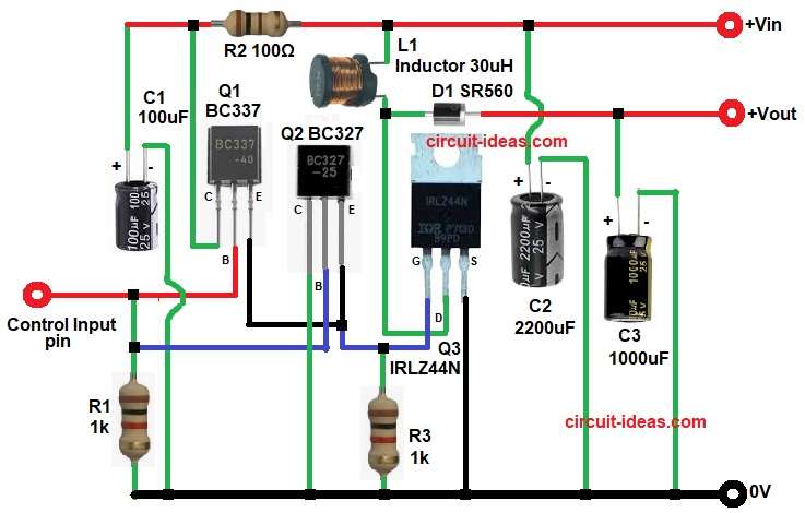
Parts List:
| Components | Values | Quantity |
|---|---|---|
| Resistors | 1k 1/4 watt | 2 |
| 100Ω 1/4 watt | 1 | |
| Capacitors | Electrolytic 100uF, 1000uF 25V, 2200uF 25V | 1 each |
| Semiconductors | Transistors BC337, BC327 | 2 |
| MOSFET IRLZ44N | 1 | |
| Inductor 30uH | 1 | |
| Diode SR560 | 1 |
At first, capacitor C1 protects circuit from voltage spikes and improves overall performance and Vin comes into the circuit and passes through R2 and C2 which help in filtering noise, then control input pin gives signal to transistor Q1 and starts circuit operation and inductor L1 stores energy when current flows through it and next, Q1 and Q2 transistors control the switching of the MOSFET Q3.
When input signal comes at pin 2 then Q1 turns ON, then it drives Q2, after that Q2 controls the gate of MOSFET Q3 through resistor R3, now MOSFET Q3 starts conducting strongly because it has low on resistance.
Meanwhile, L1 builds magnetic energy, when MOSFET turns OFF, L1 releases stored energy through diode D1 to the output, then capacitor C3 smooths the output voltage and reduces ripple.
So, result is circuit gives more current at output, before only 500mA, but now it can give near about 4A and this depend on which components we use.
Note:
The circuit input voltage Vin is approx 12V and Vout is also approx 11V to 12V which is the small drop due to components.
however, if circuit works in boost mode (with switching) then voltage can increase depending on duty cycle.
For Example:
Vin is 12V and Vout can be same as Vin or slightly higher if boost action is present.
How to Build:
To build a External Current Booster Circuit using Transistor and MOSFET follow the below connection steps:
- First, start circuit by collecting all components as shown in diagram above.
- Then start with pin Vin and connect input supply here and also connect capacitor C2 near this pin for filtering purpose.
- After that, take input control pin and connect control signal or regulator output here and this will drive transistor Q1.
- Then come to Q1 transistor, base connects to input control pin.
- Collector connects between capacitor C1 and resistor R2.
- Emitter connects to emitter of Q2 and also to gate of MOSFET Q3.
- Next, take Q2 transistor, base connects between input control pin and one side of resistor R1.
- Collector connects to ground.
- Emitter connects to emitter of Q1 and also to gate of MOSFET.
- After that, connect MOSFET Q3 gate connects to Q1 and Q2 and also one end of resistor R3.
- Drain connects to one side of inductor L1 and anode of diode D1.
- And source connects to ground.
- Then take inductor L1 with one side connect to Vin line and other side connects to MOSFET drain.
- Next, diode D1 anode connects to MOSFET drain and cathode connects to output.
- Finally, take output pin Vout and connect load here and also connect capacitor C3 across output with positive to output and negative to ground for smoothing.
Conclusion:
To conclude, this External Current Booster Circuit using Transistor and MOSFET increases current capacity from 500mA to around 4A easily, which uses a MOSFET as main current handling device.
Also, transistors control switching efficiently, moreover, inductor and diode help in energy transfer.
So, this design works well for high current applications and finally we can modify component values to adjust current and voltage as needed.