This High Current 5V 3A Voltage Regulator Circuit gives regulated 5V output with high current capacity.
Normal 7805 IC gives around 1A current, but in many projects, this current is not enough, so we add a power transistor to increase current up to around 3A.
This circuit also uses bridge rectifier and filter capacitors to convert AC to DC and smooth it.
It is simple, low cost and useful circuit for power supply applications.
Circuit Working:
Parts List:
| Components | Values | Quantity |
|---|---|---|
| Resistor | 3.3Ω 1W | 1 |
| Capacitors | Electrolytic 2200µF 25V | 3 |
| Electrolytic 10µF 25V, 100µF 25V | 1 each | |
| Ceramic 0.1µF | 1 | |
| Semiconductors | Voltage Regulator IC 7805 | 1 |
| Power Transistor MJ2955 | 1 | |
| Bridge Diodes 1N5402 | 4 | |
| Fuse 1A | 1 | |
| On-Off switch | 1 | |
| Step-down transformer primary 230V AC mains , secondary 9V AC or 12V AC 3A, output 5V 3A | 1 | |
| Heatsink for IC 7805 and transistor MJ2955 | 1 |
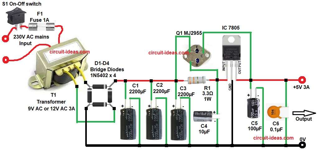
First, AC input goes from 9V AC or 12V DC through S1 and F1 fuse to bridge rectifier using diodes D1 to D4 and these diodes convert AC into pulsating DC.
Next, capacitors C1, C2 and C3 filter the ripple and make smoother DC voltage.
This DC goes to the input of 7805 IC through resistor R1, the 7805 regulates voltage and gives fixed 5V output.
The transistor Q1 MJ2955 works as current booster, when load current increases then transistor supplies extra current.
The base of transistor is connected to input side of 7805 through resistor and the emitter gives output along with 7805 output.
Capacitor C4 improves stability at input of IC and capacitors C5 and C6 remove noise at output side and give stable 5V.
So finally, circuit gives regulated 5V with higher current than normal 7805.
How to Build:
To build a High Current 5V 3A Voltage Regulator Circuit follow the below connection steps:
- Circuit starts by gathering all the components as in diagram above.
- Then start with 230V AC mains which connect to step-down transformer primary side through fuse F1 and S1 switch and this transformer converts 230V AC to 9V AC or 12V AC.
- Transformer secondary take two wires from transformer secondary 9V AC or 12V and connect these two wires to bridge rectifier AC inputs.
- Bridge Rectifier D1–D4 connect 4 diodes 1N5402 in bridge form.
- Two opposite points connect to AC input from transformer and other two points goes to DC output: positive (+) and negative (GND).
- Then start with filter capacitors C1, C2, C3 connect capacitors 2200µF across DC output with positive pin goes to DC positive line and negative pin goes to GND
- Resistor R1 connect from filtered DC positive line and other end goes to input pin of 7805.
- Then start with 7805 IC and connect pin input from resistor R1, pin ground to ground line and pin output to 5V output line
- Input capacitor C4 connect to near 7805 input.
- Output capacitors C5, C6 connect from output line and to GND line.
- Then start with Q1 transistor MJ2955 collector pin connect to output line of IC and positive of capacitor C5.
- Base pin connect between input line of IC and resistor R1 one end.
- Emitter pin connect to input line of IC and positive side of capacitor C3.
Conclusion:
This High Current 5V 3A Voltage Regulator Circuit gives simple and effective way to get high current 5V supply.
It improves standard 7805 performance by using a power transistor, as it is easy to build, good for hobby and practical use.
Proper heat sink is very important for both IC and transistor and with correct components, this circuit gives stable and reliable output.
Leave a Reply