This article for How to Convert a Speaker into a MIC Circuit shows how to turn a speaker into a microphone, as it uses the speaker to catch sound and the sound turns into a weak signal.
Furthermore, this transistor circuit makes the signal stronger, but the mic wont be very clear but it is a fun way to learn how mics work.
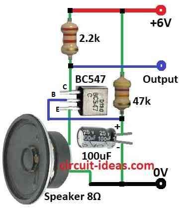
Circuit Working:
Parts List:
| Components | Values | Quantity |
|---|---|---|
| Resistors (All resistors are 1/4 watt unless specified) | 2.2k | 1 |
| 47k | 1 | |
| Capacitors | Electrolytic 100µF 25V | 1 |
| Semiconductors | Transistor BC547 | 1 |
| Speaker 8Ω | 1 | |
| Power supply +6V | 1 |
This circuit is a simple microphone amplifier that lets a speaker work like a basic mic, but it has some limits.
Real electret microphones use a special charged part and need extra voltage to work but here, the speakers coil acts like a variable resistor.
When sound hits the speaker it moves the cone and changes the coils resistance and this change creates a small voltage which the transistor boosts.
How it works:
The speaker coil acts as the mic and sound moves the cone, changing coil resistance.
A 47k resistor sets the transistors bias current and the 2.2k resistor and 100uF capacitor block DC from the output.
Hence, the BC547 transistor amplifies the weak signal.
Limitations:
Speakers do not function well as microphones, so they produce low-quality audio that may contain noise or distortion.
There is no filter to remove extra noise, as this is not good for high quality audio but it is a fun way to learn how mic amplifiers work.
Formulas:
Turning a speaker into a microphone involves using it to pick up sound and then amplifying the signal.
To build this MIC circuit using a BC547 transistor we can use these basic formulas:
1. Base Resistor RB:
This resistor controls the base current IB to the transistor:
RB = (Vin − VBE) / IB
- Vin is the voltage at the transistor base
- VBE is the voltage drop from base to emitter which is usually 0.7V
- IB is the desired base current
2. Emitter Resistor RE:
This optional resistor helps keep the transistor stable:
RE = (Vsupply − VCE(sat)) / IE
- Vsupply is the power supply voltage e.g. 6V
- VCE(sat) is the voltage drop from collector to emitter when fully on
- IE is the emitter current
3. Coupling Capacitor C:
This capacitor passes the audio signal while blocking DC:
C = 1 / (2πfR)
- f is the lowest frequency we want to pass
- R is the resistance for the next stage with input impedance
Notes:
Use resistors to properly bias the BC547 transistor and use a capacitor to send the audio signal forward without DC.
These formulas help guide our design and test the circuit and tweak component values for best results.
How to Build:
How to Convert a Speaker into a MIC Circuit following are steps we need to follow for components connections:
Power Supply:
- First, the positive terminal of a 6V supply connects to the collector of the BC547 transistor.
Speaker as Microphone:
- Then the positive wire of the speaker coil connects to the emitter of the BC547 and the negative wire of the speaker coil goes to ground.
Bias and Amplification:
- A 47k resistor connects from the base to the collector of the BC547 and a 2.2k resistor connects between the collector and the positive power supply.
- Hence, these resistors set the bias current for the transistor.
Output Coupling:
- Next, a 4.7k resistor connects from the base of the transistor through a 100uF capacitor and the negative side of the capacitor goes to ground.
- Also, this design allows the audio signal to pass while blocking DC.
Note:
- Therefore, this circuit allows a speaker to function as a simple microphone, but it delivers limited sound quality.
Conclusion:
To conclude, speakers do not pick up sound clearly, so they often produce distorted or uneven audio; also they lack filtering, which allows background noise to enter the recording.
Converting a speaker into a microphone circuit is a fun learning project, but it does not deliver high-quality sound recording, but for better results, use a real microphone.
Leave a Reply