In this article, I will explain How to Replace IC TDA2050 with LM1875 IC in Audio Amplifier Circuit.
Many people use TDA2050 for 35W amplifier, but it is considered obsolete and has been discontinued by the original manufacturer but it might be available in online market as many user wants this IC for better sound quality.
In this circuit we have used IC IC LM1875 which uses dual power supply of +18V and −18V but user can use ±15V to ±22V, but ±18V gives best performance.
Output power becomes lower and IC LM1875 gives around 20W to 25W output, so sound quality becomes better and distortion becomes low.
In that case, LM1875 IC gives good option, as both IC have same pin configuration and user can replace easily.
Below is the table for key differences in both the ICs.
| Features | IC LM1875 | IC TDA2050 |
|---|---|---|
| Output Power | ~20–30W | ~30–50W |
| Audio Quality | Lower distortion (cleaner sound) | Slightly higher distortion |
| Supply Voltage Range | Works best from ±10V to ±25V | Works from ±6V to ±25V |
| Heat Dissipation | Moderate heating | Higher heat at full power |
| Pin Compatibility | Same (5-pin package) | Same (5-pin package) |
| Best Use Case | High-quality audio, low distortion | Higher power output applications |
| Availability | It is readily available in all markets | considered obsolete might be available online |
Circuit Working:
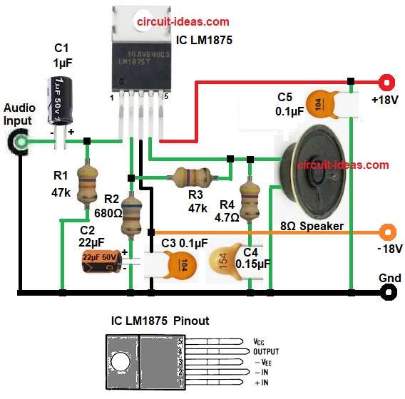
Parts List:
| Components | Values | Quantity |
|---|---|---|
| Resistors (All resistors are 1/4 watt) | 47k | 2 |
| 680Ω | 1 | |
| 4.7Ω | 1 | |
| Capacitors | Ceramic 0.15µF | 1 |
| 0.1µF | 2 | |
| Electrolytic 1µF 50V | 1 | |
| 22µF 50V | 1 | |
| Semiconductors | Speaker 8Ω | 1 |
| IC LM1875 | 1 |
Here, the circuit uses dual power supply (+V, GND, −V) for IC LM1875 whose safe and common choice is
+V = +18V and −V = −18V, do not use single power supply unless you modify this circuit and also always use proper heatsink.
Hence, the circuit works as non-inverting audio amplifier, as the input signal comes through capacitor C1 and this capacitor blocks DC and allows only AC audio signal and resistor R1 gives bias to non-inverting input.
Next, IC amplifies signal, feedback network controls gain, resistor R3 and R2 decide gain of amplifier and capacitor C2 improves low frequency response.
After that, output comes from pin 4 of IC, Zobel network R4 and C5 stabilizes amplifier and prevents oscillation and capacitors C3 and C4 filter power supply noise.
Finally, when user gives audio input then IC increases signal power and drives 8 ohm speaker.
How to Build:
How to Replace IC TDA2050 with LM1875 IC in Audio Amplifier Circuit following are the connection steps:
- First, collect all the circuit parts as in diagram above.
- Next, start with pin 1 of IC Non-inverting input and connect input signal through 1uF capacitor.
- And connect R1 resistor to ground.
- After that, take pin 2 Inverting input and connect R2 to ground through capacitor C2.
- Then take pin 3 Negative supply and connect to -V example -18V and add C2 capacitor to ground
- Next, take pin 4 Output and connect to one end of speaker 8 ohm and other end to ground and connect resistor R4 and capacitor C5 to ground.
- Also, connect feedback resistor R3 between pin 2 and pin 4 of IC.
- Lastly, take pin 5 Positive supply and connect to +V example +18V and add C3 capacitor to ground.
Important Notes:
- Use good heat sink for LM1875
- Use dual power supply for best result
- Do not exceed voltage rating
- Check all connections before power ON
Conclusion:
User can replace TDA2050 with LM1875 in same circuit without major change as both IC share same pin layout, so replacement becomes easy.
Furthermore, IC LM1875 gives lower power but better sound clarity and this IC suits home audio and small speaker system.
Also, if user wants high power then TDA2050 works better but availability of this IC is bit difficult and if user wants clean sound then LM1875 becomes good choice.
Leave a Reply