This project shows how we can use a normal speaker as a microphone and usually, a microphone converts sound into electrical signals.
However, a speaker can also do the same work in reverse, therefore, this circuit becomes a simple and low-cost solution when we do not have a microphone.
Moreover, it works well for basic audio experiments and small amplifier stages.
Circuit Working:
Parts List:
| Components | Values | Quantity |
|---|---|---|
| Resistors (All resistors are 1/4 watt unless specified) | 2.2M, 5.6k, 2.2k | 1 each |
| 8.2Ω 1/2 watt | 1 | |
| Capacitors | Electrolytic 220µF 25V | 2 |
| Electrolytic 100µF 25V | 1 | |
| Semiconductors | Transistors BC547 (or equivalent BC109C, BC548) | 2 |
| Speaker 8Ω | 1 | |
| Power Supply 9V Battery | 1 |
First, speaker works like microphone and when sound hits speaker cone, it moves and makes small electrical signal.
Then, capacitor C1 passes only AC signal and blocks DC, after that signal goes to emitter of transistor Q1.
Next, resistor R1 gives bias to Q1, at same time resistor R3 keeps emitter current stable, so Q1 amplifies weak signal from speaker.
After that, amplified signal goes to transistor Q2 and here, Q2 amplifies more, meanwhile, resistor R2 sets correct bias for Q2 and resistor R4 controls current.
Then, capacitor C3 sends output signal and it blocks DC and allows only amplified AC signal to go to output.
Finally, we get stronger audio signal at output terminal.
How to Build:
To build a Low Cost DIY Microphone Circuit using Normal Speaker following are the connection steps:
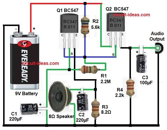
- Start, by gathering all the circuit parts as in diagram above.
- Next, take transistor Q1 and connect base to resistor R1 and capacitor C1 positive and negative to ground.
- Then connect emitter to resistor R3 and negative of capacitor C2 and positive end to one end of 8 ohms speaker and ground.
- After that connect collector to the junction of R1, R2 and transistor Q2 base.
- Next, take transistor Q2 and connect base to collector of Q1.
- Then connect collector to positive supply of +9V battery.
- After that connect emitter to resistor R4 and positive of capacitor C3 and negative goes to OUPUT.
- Finally, connect power supply use 9V battery and connect positive to R2 and negative to ground.
Conclusion:
Overall, this Low Cost DIY Microphone Circuit using Normal Speaker gives a simple way to use a speaker as a microphone.
Also, it uses only a few components, so we can build it easily, moreover, it works well for learning basic audio electronics.
However, sound quality may not match a real microphone, but still for experiments and small projects, it gives a good and useful result.