Here, is very simple and useful mini light intensity meter circuit using LDR which uses one LM334 IC, one LDR, small analog milliamp meter and 1.5V battery or power supply.
The circuit checks light level by changing meter current as per LDR resistance.
When light increases, LDR resistance changes so meter needle moves, because of this circuit helps check light intensity in simple and low-cost way.
Also, circuit uses very few parts, so beginners can make it easily for school project, hobby electronics and basic light sensing use.
Circuit Working:
Parts List:
| Components | Values | Quantity |
|---|---|---|
| Resistor | LDR | 1 |
| Semiconductors | LM334 IC | 1 |
| Ammeter 0–1mA analog meter | 1 | |
| Power Supply 1.5V battery or cell | 1 |
The circuit works on the resistance change property of the LDR, first the LDR senses the surrounding light and then it changes its resistance value.
When the light falls on the LDR, its resistance decreases and as a result, the LM334 allows more current flow.
Then the analog meter shows a higher reading and on the other hand, when the light becomes low or dark the LDR resistance increases, then the current flow reduces and therefore, the meter needle moves toward a lower reading.
In this way, the meter directly indicates the light level.
Also, the LM334 acts like an adjustable current source, because of this, the current depends mainly on the resistor connected to its R pin, which in this circuit is the LDR.
How to Build:
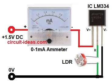
To build a Mini Light Intensity Meter Circuit using LDR follow the below connection steps:
- Start, the circuit by collecting all the parts as shown in above circuit diagram.
- Next , start with IC LM334 and connect pin 1(R) to one terminal of the LDR and other end of LDR connect to ground.
- Then take pin 2 (V+) and connect to the negative side of the analog ammeter and connect the positive side of the ammeter to +1.5V battery.
- After that take pin 3 (V-) and connect pin 3 directly to ground or battery negative.
Conclusion:
This simple mini light intensity meter circuit using LDR gives easy way to check light level with very few parts.
When light changes, the LDR changes resistance, then LM334 changes it into current and the analog meter shows clear reading.
Also, the circuit uses only 1.5V supply, so it stays compact and uses low power and therefore, it is very good project for beginners and hobby users.
Leave a Reply