The MQ2 Gas Sensor Circuit with Arduino is a low-cost sensor, as it can catch bad gas in air very quickly.
When we connect it with Arduino, we make small gas alarm system; it reads gas level, show number on LCD and buzzer make sound when gas goes high.
Also, this circuit is very simple to make and easy to learn and it is good project for basic gas detection using Arduino.
Arduino Code:
#include <Wire.h>
#include <LiquidCrystal_I2C.h>

LiquidCrystal_I2C lcd(0x27,16,2);

int sensorPin = A0;
int buzzerPin = 8;
int gasValue = 0;
int limitValue = 300;

void setup() {
lcd.init();
lcd.backlight();
pinMode(buzzerPin, OUTPUT);
}

void loop() {
gasValue = analogRead(sensorPin);
lcd.setCursor(0,0);
lcd.print("Gas: ");
lcd.print(gasValue);

if(gasValue > limitValue){
digitalWrite(buzzerPin, HIGH);
lcd.setCursor(0,1);
lcd.print("Gas High! ");
} else {
digitalWrite(buzzerPin, LOW);
lcd.setCursor(0,1);
lcd.print("Safe ");
}
delay(300);
}
Coding Explanation:
- LCD library works with I2C LCD.
- SensorPin reads analog gas value from MQ2.
- BuzzerPin becomes HIGH when gasValue is more than limitValue.
- LCD shows gasValue and warning message.
- Delay slows loop to read clearly.
Circuit Working:
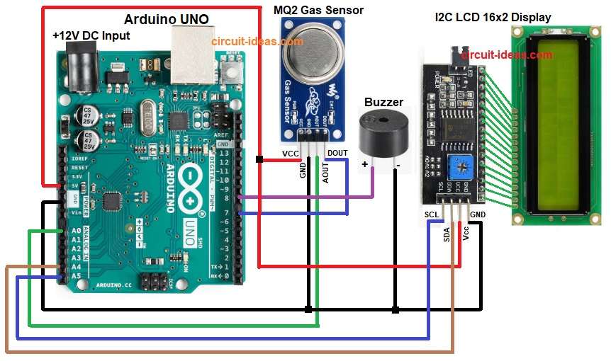
Parts List:
| Components | Quantity |
|---|---|
| Arduino UNO | 1 |
| MQ2 Gas Sensor | 1 |
| Buzzer 5V | 1 |
| I2C LCD 16×2 Display | 1 |
To begin with, MQ2 has heater and sensor resistor and when gas increases, sensor resistance falls; then Arduino reads this as higher analog value.
After that, code checks value and if value is high then buzzer turns ON and LCD shows alert.
Formulas:
Below is the formula for MQ2 Gas Sensor Circuit with Arduino:
MQ2 output = voltage across load resistor RL.
Vout = (RL / (RL + RS)) * VCC
where,
- RL is the load resistor which is a fixed resistor on the sensor.
- RS is the sensor resistance which changes when gas level changes.
- VCC is the supply voltage of 5V.
When gas level rises, RS becomes small so Vout becomes high.
How to Build:
To build a MQ2 Gas Sensor Circuit with Arduino follow the below steps:
- First, take all the parts as shown in circuit diagram.
- Next, MQ2 VCC pin connect to Arduino 5V, MQ2 GND pin connect to Arduino GND, MQ2 AO pin connect to Arduino A0 and MQ2 DO pin connect to Arduino digital pin D7
- Then buzzer positive connect to Arduino pin and buzzer negative connect to GND
- Now I2C LCD VCC pin connect to 5V and I2C LCD GND pin connect to GND
- After that, I2C LCD SDA pin connect to Arduino A4 and I2C LCD SCL pin connect to Arduino A5
Conclusion:
To conclude, this is simple project for MQ2 Gas Sensor Circuit with Arduino and then Arduino read sensor value and give warning by buzzer and LCD.
Also, this project is good for safety and for basic learning.

Leave a Reply