A Gas Alarm Circuit using an MQ Sensor and a buzzer gives a quick warning when the gas level becomes dangerous; also the MQ Sensor quickly detects a gas leak, and the buzzer produces a loud sound when it detects gas.
Moreover, circuit runs on 5V and uses very few parts and it is good for low-cost safety at home, kitchen and workplace.
Circuit Working:
Parts List:
| Components | Values | Quantity |
|---|---|---|
| Resistors | 1k 1/4 watt | 1 |
| Preset 10k | 1 | |
| Capacitor | Electrolytic 22uF 25V | 1 |
| Semiconductors | IC LM3915 | 1 |
| Gas Sensor Module MQ-2 Module | 1 | |
| LEDs any | 10 | |
| Buzzer 5V | 1 | |
| On/Off Switch SPST Switch | 1 |
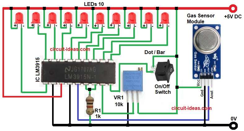
In the above circuit diagram the MQ Gas Sensor gives an analog voltage; then voltage increases when gas level increases.
After that, voltage goes to Pin 5 of LM3915 and this LM3915 works like a voltage meter and lights LEDs from low to high.
More gas means more LEDs turn ON and the 10k preset sets sensitivity and also the 1k resistor sets reference level.
Finally, the Dot/Bar pin selects Dot Mode or Bar Mode.
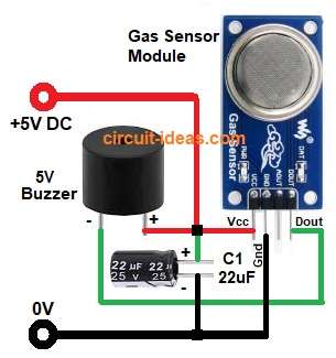
In the above circuit diagram the sensor output drives the buzzer, and when sensor output goes high because of gas the buzzer gets power and makes sound.
Finally, the 22uF capacitor smooths the signal so buzzer sound becomes steady.
Formulas with Calculation:
Below is the formula with calculation for Gas Alarm Circuit using MQ Sensor and Buzzer:
LM3915 reference current Ir = 12.5V / R1
If R1 = 1k then Ir = 12.5V / 1000 = 0.0125A
LED current is almost same as Ir, so each LED gets around 12mA and sensor output Vo increases with gas and then LM3915 lights each level at 125mV step.
Step voltage = Vref / 10
If Vref = 1.25V then step = 1.25 / 10 = 0.125V
How to Build:
To build a Gas Alarm Circuit using MQ Sensor and Buzzer follow the below steps:
- First, collect all parts same as circuit diagram.
- Next, connect MQ Sensor Module VCC pin to +5V, connect GND pin to Ground and connect Aout pin to LM3915 pin 5.
- After that, LM3915 pins 1,10,11,12,13,14,15,16,17,18 go to LED cathode and LED anode side go to +5V.
- Then pin 2 of IC LM3915 go to GND and pin 3 go to +5V.
- Now pin 4 goes to GND and Pin 5 go to Aout pin of MQ Sensor.
- Further, pin 6 and pin 7 join through with 1k resistor.
- Also, pin 8 go to ground and pin 9 go to switch one end and other switch end goes to +5V for Dot or Bar Mode.
- 10k preset first pin go to GND, second pin go to pin 8 and third pin go to +5V.
- Next, buzzer positive pin goes to +5V and buzzer negative go to DOUT pin of MQ Sensor.
- 22uF capacitor positive side goes to +5V and negative side go to GND.
Conclusion:
To conclude, this system gives simple and low-cost gas indicator with no microcontroller and IC LM3915 shows gas level on LEDs and then buzzer gives quick alarm when gas comes.
Also, circuits is easy to make using 5V supply and common parts.

Leave a Reply