Here is the tutorial for small circuit with big sound; this Op Amp 741 Sound Generator Circuit creates stable tone for hobby projects.
The Op amp works like mini sound machine with no complex parts and with no hard wiring, just connect parts and enjoy instant sound in just few minutes.
Also, this circuit is good for alarms, buzzer and learning electronics.
Circuit Working:
Parts List:
| Components | Values | Quantity |
|---|---|---|
| Resistors (All resistors are 1/4 watt | 15k, 3.3k,10k | 1 each |
| Preset 20k to 22k | 1 | |
| Capacitor | Ceramic 10nF | 1 |
| Semiconductors | IC 741 Op Amp | 1 |
| Transistor BC547 | 1 | |
| Speaker 8Ω | 1 |
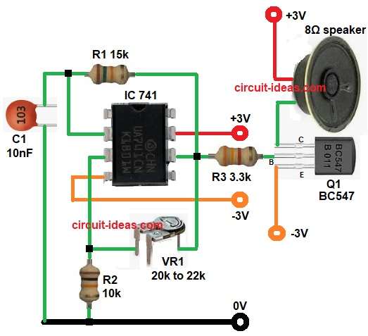
To begin with, the op amp works in astable multivibrator mode and it makes continuous square wave signal around 3KHZ frequency; hence, square wave creates audio tone.
Then capacitor C1 and resistors R1, VR1, R2 decide the frequency; after that op-amp output goes to transistor Q1 and Q1 drives the a small 8Ω speaker.
Then R3 limits current going to Q1 and then speaker gives sound when square wave comes.
Formula with Calculation:
Frequency formula:
f = 1.44 / ((R1 + 2R2(VR1)) × C1)
Values:
- R1 is 15000 ohm
- R2(VR1) is 16500 ohm
- C1 is 10 × 10⁻⁹ F
Substitute:
f = 1.44 / ((15000 + 2 × 16500) × 10 × 10⁻⁹)
Step by step:
2 × R2 = 33000
R1 + 2R2(VR1) = 48000
Multiply by C1: 48000 × 10 × 10⁻⁹ = 0.00048
Divide: 1.44 / 0.00048 = 3000 Hz
Note:
Use a 22k or 20k preset for VR1, then adjust it slowly until the tone becomes around 16.5k which gives 3 kHz; also we can adjust tone higher or lower anytime which is much easier to match our target of 3 kHz.
How to Build:
To build a Op Amp 741 Sound Generator Circuit follow the below steps:
- First, gather all the parts as shown in circuit diagram.
- Next, pin 2 is inverting input connect between R1 and C1 network.
- After that, pin 3 is non-inverting input connect between VR1 and R2 resistors.
- Then pin 6 is output of op-amp which goes to transistor through R3.
- Also, pin 7 goes to positive supply +3V and pin 4 goes to negative supply -3V.
- Now transistor Q1 BC547 drives the speaker and then speaker connects between +3V and collector of Q1, emitter goes to -3V and base of transistor goes to pin 6 of IC through resistor R3.
Conclusion:
Overall, this Op Amp 741 Sound Generator Circuit is simple and easy and it uses few parts only which are easily available in market.
Frequency can change by changing R1, VR1, or C1 and also this circuit it is good for hobby, testing, learning sound basics and works on low voltage and is safe for beginners.

Leave a Reply