Want a simple sound maker? then make noise with this electronic circuit; this small circuit makes loud beep sound from speaker using only one 555 timer, then the circuit turns 9V battery into instant audio tone.
Also, this Audio Sound Generator Circuit using IC 555 is easy to build and is great for learning.
Circuit Working:
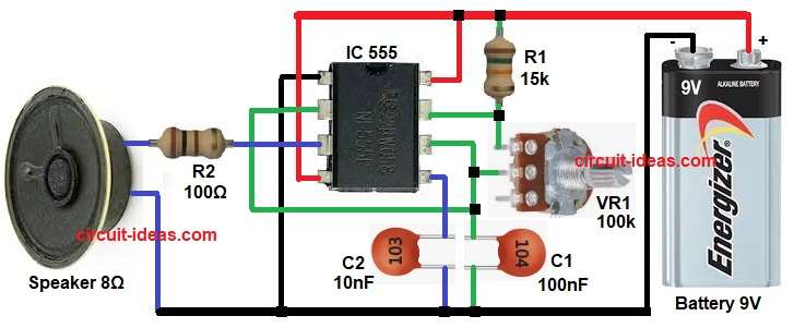
Parts List:
| Components | Values | Quantity |
|---|---|---|
| Resistors (All resistors are 1/4 watt) | 15k, 100Ω | 1 each |
| Potentiometer 100k | 1 | |
| Capacitors | Ceramic 100nF, 10nF | 1 each |
| Semiconductors | IC 555 | 1 |
| Speaker 8Ω | 1 | |
| Battery 9V | 1 |
The 555 timer works in astable multivibrator mode and this astable mode 555 makes continuous square wave, also this square wave drives the 8Ω speaker.
The circuit has an oscillation frequency about 670 to 680 HZ and then the sound frequency can change easily and we can change R1, VR1 or C1; and also any change in these parts will shift the tone.
R1, VR1 and C1 decide the tone frequency and then VR1 will increase or decrease the frequency and we will get rising or falling beep sound.
Moreover, it becomes easy to tune the audio tone anytime and then C2 is noise filter capacitor and R2 limits speaker current and protects IC.
Formula with Calculation:
The frequency formula is:
f = 1.44 / ((R1 + 2R2) × C1)
Circuit values as in circuit:
- R1 is 15k
- R2 (VR1) is 100k
- C1 is 10nF
Now convert units as:
R1 = 15000Ω
R2(VR1) = 100000Ω
C1 = 10 × 10^-9 F
Now calculate step by step:
R1 + 2R2 = 15000 + 200000 = 215000 Ω
f = 1.44 / (215000 × 10 × 10^-9)
f = 1.44 / 0.00215
f = 670 Hz
So the sound is around 670 Hz and this gives a simple normal beep tone.
How to Build:
To build a Audio Sound Generator Circuit using IC 555 follow the below steps:
- First, assemble all the parts as shown in circuit diagram.
- Next, pin 1 of IC 555 connect to ground.
- Then pin 2 connect to junction of VR1 and C1.
- After that, pin 3 output pin connect to R3 and then to speaker.
- Now pin 4 reset pin connect to positive supply and then pin 5 control voltage connect C2 to ground.
- Also, pin 6 threshold pin connect to pin 2.
- Further, pin 7 discharge pin connect to R1 and VR1 top point.
- Pin 8 Vcc connect to 9V positive.
- Finally, speaker LS connects between R3 and ground and battery 9V connects to Vcc and ground.
Conclusion:
Overall, this Audio Sound Generator Circuit using IC 555 is simple and easy to make, as it uses few parts and makes stable beep sound.
Also, it is good for hobby projects, alarms, toys and learning electronics and anyone can build easily on breadboard or PCB.

Leave a Reply