Simple 0-9 Counter Circuit with 7-Segment Display show numbers from 0 to 9.
It is used in digital counters, clocks and measuring tools.
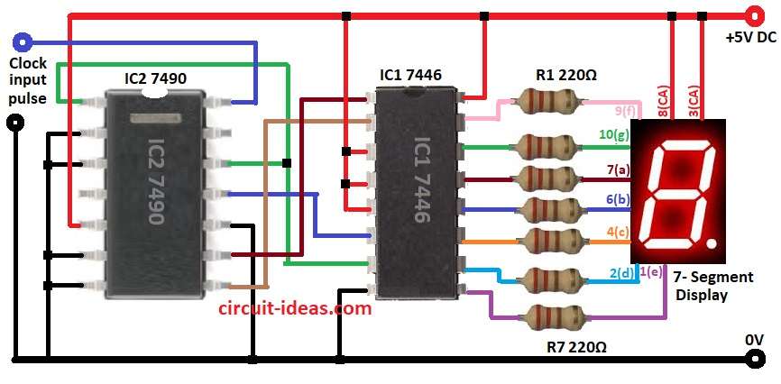
Main parts of this circuit are 7490 Decade Counter IC, 7446 BCD to 7-segment Driver IC.
It works with Common Anode 7-segment display with all LED positives joined.
Circuit is powered by 5V DC and runs a whole system.
Circuit Working:
Parts List:
| Component | Quantity |
|---|---|
| Resistors | |
| 1/4 watt 220Ω | 7 |
| Semiconductors | |
| IC 7446 | 1 |
| IC 7490 | 1 |
| 7-Segment Common Anode Display | 1 |
IC 7490 is decade counter which count from 0 to 9.
It gets clock pulse and gives BCD output.
This BCD output goes to IC 7446.
IC 7446 changes BCD to signals for 7-segment display.
7446 outputs connect to display using resistors.
Common anode 7-segment display used to show 0 to 9.
Display connect to IC 7446 through 220Ω resistors from R1 to R7.
Resistors control current to display.
Clock pulse goes to pin 14 of IC2.
Each pulse of IC 7490 count increase by 1.
Formulas with Calculations:
Formulas and calculations for 0 to 9 counter circuit are shown below:
Resistors R1 to R7 control current to 7-segment.
Use ohms law to find value:
R = (V – Vf) / I
where:
- V is the 5V for power supply
- Vf is the 2V for LED forward voltage
- I is the 15mA LED current
How to Build:
To build a Simple 0-9 Counter Circuit with 7-Segment Display follow the below steps:
- Gather all parts shown in circuit diagram.
- Connect pin 1 of IC2 7490 to pin 12 of IC2 and pin 7 of IC1 7446.
- Connect pins 2, 3, 6, 7, 10 of IC2 to GND.
- Connect pin 8 of IC2 to pin 2 of IC1.
- Connect pin 9 of IC2 to pin 1 of IC1.
- Connect pin 11 of IC2 to pin 6 of IC1.
- Connect pin 5 of IC2 to +5V DC.
- Connect pins 3, 4, 5, 16 of IC1 to +5V DC.
- Connect pin 8 of IC1 to GND.
- Connect display pins to IC1 through resistors:
- Pin 13 of IC1 connects to display pin 7(a) through R3
- Pin 12 connects to display pin 6(b) through R4
- Pin 11 connects display pin 4(c) through R5
- Pin 10 connects to display pin 2(d) through R6
- Pin 9 goes to display pin 1(e) through R7
- Pin 15 goes to display pin 9(f) through R1
- Pin 14 goes to display pin 10(g) through R2
- Connect pin 8 and pin 3 (CA) of display to +5V of common anode.
- Pin 14 of IC2 gets clock pulse input.
Conclusion:
This Simple 0-9 Counter Circuit with 7-Segment Display shows how BCD counter, decoder IC and 7-segment work together.
It is used in many projects like timers, counters and event tracking.
7446 IC makes display connection easy and system works smoother.
Leave a Reply