Amplifiers play a useful and important role in audio systems, as they give power to speakers and keep sound good; also, this 150 Watt Audio Amplifier Circuit using Transistors gives 150W output.
Moreover, it uses two Darlington transistors like TIP142 and TIP147 and it is good choice and works well with low cost and is best for 8 ohm speaker.
The circuit is a simple design and easy to get parts and also the circuit is great for DIY and electronics lovers.
Circuit Working:
Parts List:
| Components | Values | Quantity |
|---|---|---|
| Resistors (All resistors are 1/4 watt unless specified) | 1.5k | 1 |
| 27k | 1 | |
| 220Ω | 1 | |
| 33Ω | 1 | |
| 22k | 2 | |
| 3.3k 1 watt | 2 | |
| 0.33Ω 7 watt | 2 | |
| Capacitors | Electrolytic 10μF, 25V | 2 |
| Electrolytic 100μF, 25V | 1 | |
| Semiconductors | Transistor TIP142 | 1 |
| Transistor TIP147 | 1 | |
| Transistor TIP41 | 1 | |
| Transistor BC557 | 2 | |
| Diode 1N4007 | 2 | |
| Speaker 8Ω 15 Watt | 1 |
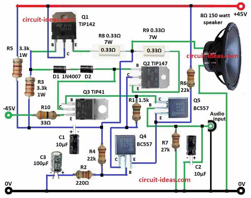
Circuit has many parts: transistors TIP142, TIP147, TIP41, BC557, also resistors, capacitors, diodes and speaker, as it uses complementary Darlington pair.
Furthermore, this design give more current and clean sound and its audio comes in through Audio IN.
Also, capacitor C2 block DC and only AC (audio) goes through and signal goes to Q5 which is the preamp and Q5 make signal stronger.
Then signal goes to Q4 which send power to Q1 TIP142 and Q2 TIP147 which are the the main amplifiers and TIP142 handle positive wave and TIP147 handle negative wave.
After that, resistors R8 and R9 keep current stable and stop overheating and resistors and capacitors keep bias right and circuit stable.
Here, R1, R2 set bias for Q4, Q5 and R7 give feedback and help reduce distortion and improve sound.
Finally, power comes from dual supply with +45V and -45V.
Formulas with Calculations:
This method show how to make simple 150W audio amplifier using transistors.
Output Power:
Power (RMS) = Vpeak² / 2R
where:
- Vpeak is the peak voltage
- R is the load for 8Ω speaker
Power in Resistors:
Power in R8 and R9
= I² × R
where:
- I is the current in resistor
Frequency Response:
Cutoff freq (fc) = 1 / (2πRC)
For C2 is 10µF and R7 is 27kΩ:
fc = 0.59Hz
Means its good for low bass response.
How to Build:
To build a 150 Watt Audio Amplifier Circuit using Transistors follow the below mentioned steps for connections:
- First, collect all parts as from circuit diagram.
- Next, Q1 base goes to D1 and D2 through Q2 base, Q1 collector goes to +45V and Q1 emitter connect to Q2 emitter using R8 and R9.
- Then Q2 base connect to Q1 base, Q2 collector connect to Q4 collector and then Q2 emitter connect to Q1 emitter.
- Now Q3 base connect to Q5 collector., Q3 collector connect to Q2 base and then Q3 emitter goes to -45V through R10.
- After that, Q4 base connect between R4, R2 and C3 and all go to GND, Q4 collector goes to Q5 collector through R1 and Q4 emitter connect to Q5 emitter.
- Also, C2 applies the audio input to the base of Q5, R7 connects the base of Q5 to GND and R6 connects the emitter of Q5 to +45 V.
- Further, speaker 8Ω connect between R8 and R9 and GND and C1 connect between R5, R3, R8, R9 and R4 junction; also other end of R5 goes to +45V.
Conclusion:
Overall, this 150 Watt Audio Amplifier Circuit using Transistors give good sound for mid power use and it is a simple design with strong parts and with low distortion.
Also, the circuit runs cool and last long with good testing and is best for home audio, DIY and learning.
So try different inputs and speakers for better sound.