40 Watt Audio Amplifier Circuit makes small sound signal big, so sound come out loud from speaker and we can hear music or audio more loud with this.
The main component of this easy circuit is the TDA2040 IC and this IC comes in a Pentawatt package and operates as a Class AB audio amplifier.”
Furthermore, the circuit give 40 watt output when it uses 4 ohm speaker and 36V power.
Circuit Working:
Parts List:
| Components | Values | Quantity |
|---|---|---|
| Resistors (All resistors are 1/4 watt unless specified) | 22k | 3 |
| 20k | 1 | |
| 47Ω | 1 | |
| 680Ω | 1 | |
| Capacitors | Ceramic 100nF | 2 |
| Electrolytic 1μF | 1 | |
| Electrolytic 22μF | 2 | |
| Electrolytic 220μF | 2 | |
| Semiconductors | IC TDA2040 | 1 |
| Speaker 4Ω | 1 |
To begin with, TDA2040 IC is main part of this circuit, as it can take power up to 40V and work with single or split power supply which is very flexible.
Moreover, it also have safety features like stop working if too hot or short circuit happen.
TDA2040 come in small 5-pin pentawatt case and is easy to fix on heat sink and it also have one inverting input, one non-inverting input, two power pins and one output pin.
In this 40-watt amplifier design, capacitor C1 sends the audio signal to the non-inverting input of the TDA2040; additionally, bias components ensure proper circuit operation at the input and output stages.
Then output sound goes from pin 4 through capacitor C3 to 4Ω speaker and lastly, C3 stop DC from reaching speaker but let audio AC signal pass.
Formulas:
To make 40 Watt audio amplifier with TDA2040 IC we need to think about speaker ohm, circuit design, power voltage and heat control.
Important parts and formulas:
Speaker Impedance Load:
Use 4Ω speaker.
To find output power Pout then use this formula:
Pout = Vpeak² / 2R
where:
- R is the load for 4Ω
- Vpeak is the peak voltage across speaker.
Gain Calculation:
Gain change by feedback resistors.
Formula for gain in dB:
Gain(dB) = 20 × log₁₀(Rf / Rin)
where,
- Rf is the feedback resistor
- Rin is the input resistor.
Use these formulas and tips to build TDA2040 40W amp and change parts as needed for our project goal.
How to Build:
To build a 40 Watt Audio Amplifier Circuit follow the below mentioned steps for connections and assembling.
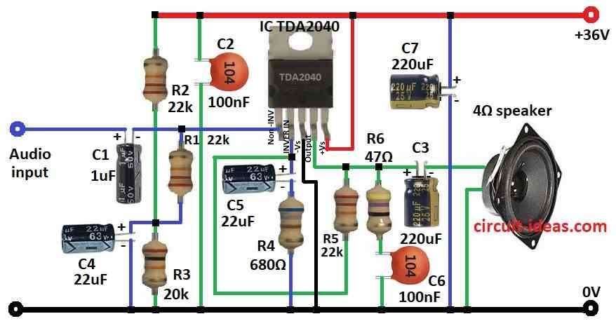
- First, put all parts same like in circuit diagram.
- Next, connect pin 1 of TDA2040 to audio input using capacitor C1.
- Then connect pin 2 to ground using capacitor C5 and resistor R4.
- Now connect pin 3 directly to ground.
- After that, connect pin 4 to one end of 4Ω speaker and other end of speaker to ground, connect resistor R5 from pin 4 to pin 2 and also connect resistor R6 and capacitor C6 from pin 4 to ground.
- Now, again connect capacitor C3 from pin 4 to speaker.
- Then connect pin 5 to +36V power and connect resistors R2 and R3 between +36V and ground.
- Also, connect capacitor C7 from +36V to ground and also connect capacitor C2 from +36V to ground.
- Lastly, connect resistor R1 and capacitor C4 from pin 1 to ground.
Conclusion:
Finally, this 40 Watt Audio Amplifier Circuit is simple to make and however, always follow safety rules and ensure we connect and solder all parts correctly according to the circuit diagram.
Leave a Reply