Have anyone ever thought that how electronic makes sound?
Audio frequency signal generator it like small sound maker, it make electric signal what ear can hear from low boom (20Hz) to very high squeaky (20kHz).
Also, this Simple Audio Frequency Signal Generator Circuit very helpful for many thing:
- Check speaker or amplifier work good or not.
- It make funny sound or music like beep-beep, zap-zap this circuit can do it!
- Test sound system like use ruler for sound and see how good system work.
Circuit Working:
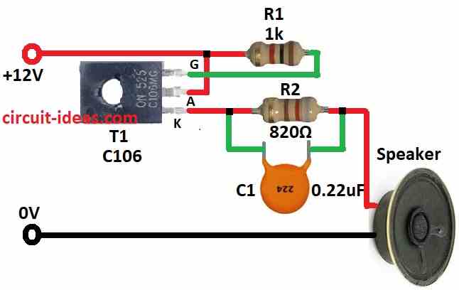
Parts List:
| Components | Quantity |
|---|---|
| Resistors | |
| 1k 1/4 watt | 2 |
| 820Ω 1/4 watt | 2 |
| Capacitor | |
| Ceramic 0.22µF | 1 |
| Semiconductors | |
| SCR C106 | 1 |
| Mini Speaker 8Ω | 1 |
To begin with, this circuit uses one thyristor, two resistor, one capacitor and small speaker to make signal.
When power is turn ON current go through R1 and turn on thyristor and then thyristor let current pass and start charging capacitor C1.
But as C1 charge more charging current go down slowly and when current gets too low thyristor turn OFF; after that C1 empty itself through R2 and whole thing start again.
Hence, thyristor keep turning ON and OFF like this and that make signal go up and down; but how fast it does this (frequency) depend on C1 and R2.
Formula:
Formula for Estimating Frequency:
We can use the following formula to approximately calculate the oscillation frequency (f) in this circuit:
f = 1 / 2 * R * C
where,
- R is resistor from RC part in ohms which help turn ON the SCR.
- C is capacitor from RC part in farads.
If one uses SCR C106 and one RC trigger setup this formula give good start to make and understand sound signal circuit; but real parts not always perfect so maybe need small change in value to make it work good in real life.
How to Build:
To build a Simple Audio Frequency Signal Generator Circuit follow the below steps required for connections:
Get All Parts:
- First, take all the parts we need that are listed in the above diagram.
Make Circuit Plan:
- After that, think how to put parts on breadboard or PCB and be sure about enough space so that wire can connect easy.
Put Thyristor (SCR):
- Next, place thyristor on board and connect like this, anode go to positive side of battery or power and cathode connect to one side of R1.
- Now gate go to middle point where R1 and power positive meet.
Add Resistor R2:
- Also, one side of R2 connects to same point where R1 and gate connect and other side of R2 connects to cathode of thyristor.
Put Capacitor C1:
- One leg of capacitor C1 connect to cathode and other leg connect to negative side of power.
Connect Speaker or Buzzer:
- It makes sound when circuit work.
Add Power:
- Connect power to the circuit, with positive to anode of thyristor and negative to other side of capacitor C1
Test the Circuit:
- Now turn ON power; speaker should make sound and beep or buzz, if not check all wires again.
- If required change value of R2 or C1 to make sound faster or slower
Be Safe:
- Use low voltage and no high power, also do not touch wire when power is ON.
Note:
- Always check twice the wire and part before turning power ON and if confused ask friend who know about electronics or find expert help.
Conclusion:
Overall, this Simple Audio Frequency Signal Generator Circuit can be simple or complex.
Also, some use just few parts like resistor and capacitor and some use big chips or microcontroller for smart work.
Hence, people use these circuits a lot for sound testing, fixing electronics or fun hobby project where sound signal needed
Leave a Reply