In this article, the circuit gives temporary backup power to low current electronic systems as it uses JFET transistor like 2N3819.
This Simple Backup Power Supply Circuit using JFET Transistor which charges a capacitor at 15V input and gives approximate 4V-6V output during power failure, because it depends on transistor characteristics, resistor tolerance and load current
First, the circuit stores energy in large capacitor C1, when main power supply is ON, the capacitor charges and then, when power supply goes OFF, the capacitor gives stored energy to the load.
Therefore, this circuit works best with very low current devices.
Circuit Working:
Parts List:
| Components | Values | Quantity |
|---|---|---|
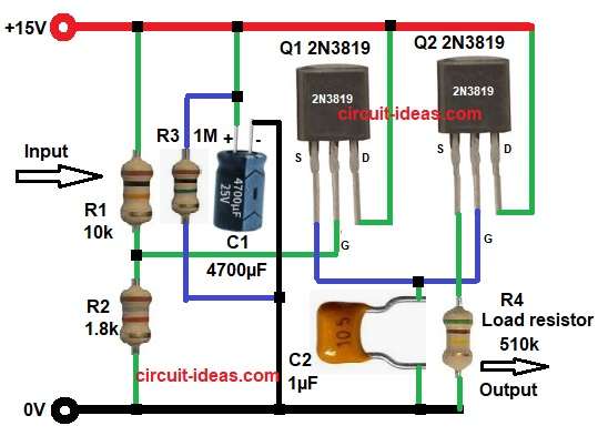
| Resistors | 10k, 1.8k, 1M, 510k | 4 |
| Capacitors | Electrolytic 4700µF 25V | 1 |
| Ceramic 1µF 50V | 1 | |
| Semiconductors | JFET Transistor 2N3819 | 2 |
| Diode 1N4007 | 1 | |
| Input Power Supply 15V DC, Output Voltage Approx 4V – 6V is not fixed |
When input supply +15V is ON the diode D1 allows current flow into the circuit, capacitor C1 starts charging slowly, resistors R1, R2 and R3 create proper bias voltage for Q1.
Q1 controls the charging path and it helps maintain proper voltage level and Q2 works as output stage, as it passes power to the load in a controlled way.
Note: For testing we can add R4 510k resistor as load and for real use remove load resistor and connect the actual circuit.
When supply is present:
- D1 allows forward current
- C1 stores energy
- Q1 and Q2 stay active
- Output voltage remains stable
When supply is removed:
- D1 stops reverse current
- C1 starts discharging
- Q2 supplies power to load
- Output voltage slowly decreases
Capacitor C2 filters noise and keeps output smooth and the circuit gives backup for short time depending on load current.
How to Build:
To build a Simple Backup Power Supply Circuit using JFET Transistor follow the below connection steps:
- Start, gathering all the components as in circuit diagram.
- Then start with JFET transistor Q1 with drain pin connect to supply line with diode D1.
- Gate pin connect to junction of R1 and R2.
- Source pin connect to node that goes to Q2 gate and one end of capacitor C2.
- Then take JFET transistor Q2 with drain pin connect to supply line.
- Gate pin connect to source of Q1 and one end of capacitor C2.
- Source pin connect to output and load resistor R4.
- Then start with D1 diode anode connect to input of +15V .
- Cathode end connect to circuit supply rail.
- Capacitor C1 4700uF positive end connect to supply rail and negative end connect to ground.
- Capacitor C2 1uF one side connect between Q1 source pin and Q2 gate pin and other end connect to GND.
- Resistors R1 and R2 connect in series from VDD input and GND.
- R3 connect in parallel with capacitor C1.
- Finally, load resistor one end connect to source pin of Q2 and other end connect to ground.
Conclusion:
This Simple Backup Power Supply Circuit using JFET Transistor provides simple and low cost backup power supply, which uses capacitor energy storage instead of battery.
The circuit is easy to build and needs very few components, as it is suitable for low current applications where short backup time is enough.
Using JFET Transistor 2N3819 gives stable and reliable operation.
Leave a Reply