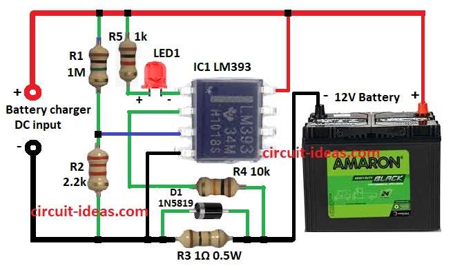
Simple Battery Charging Indicator Circuit using IC LM393 shows if battery is charging or not.
It helps stop overcharge and through this charging becomes safe and better.
Main part is LM393 comparator IC.
It turns ON LED to show charging.
Circuit is easy and cheap and is good for checking 12V lead-acid battery.
Circuit Working:
Parts List:
| Component | Value / Part Number | Quantity |
|---|---|---|
| Resistors (All resistors are 1/4 watt unless specified) | 1M | 1 |
| 2.2k | 1 | |
| 1Ω 0.5W | 1 | |
| 10k | 1 | |
| 1k | 1 | |
| Semiconductors | LM393 Comparator IC | 1 |
| 1N5819 Schottky Diode | 1 | |
| LED 5mm 20mA | 1 | |
| 12V Lead-acid Battery | 1 |
This circuit works by checking charging current through resistor R3 1Ω, 0.5W.
It measures voltage drop across R3.
LM393 comparator is main part and it controls LED1 to show charging.
Battery charger gives current to battery.
When current flows through R3 small voltage drop happens.
Diode D1 Schottky gives reference voltage.
LM393 checks voltage change.
If current is strong then LED1 turns ON and battery is charging.
When battery gets full then current drops.
Voltage drop on R3 also drops.
Comparator sees this and turns LED OFF and battery is full.
Formulas with Calculations:
To make simple battery charging indicator with LM393 use these formulas:
1. Voltage Drop on Resistor R3:
Vshunt = Icharging × R3
Example: If charging current = 1A, R3 = 1Ω
Vshunt = 1 × 1 = 1V
2. Reference Voltage from R1 & R2:
Vref = Vsupply × R2 / (R1 + R2)
Example:
If Vsupply is 12V, R1 = 1M, R2 = 2.2k
- Vref is 12V which is very small voltage set
This makes comparator work at low shunt voltage.
3. Comparator Working:
If Vshunt > Vref → Output LOW → LED ON
If Vshunt < Vref → Output HIGH → LED OFF
How to Build:
To build a Simple Battery Charging Indicator Circuit using IC LM393 follow the below steps for connections:
- Gather all the parts as per the circuit diagram
- Connect pin 1 of LM393 to LED1 negative.
- LED1 positive goes to one side of R5 and other side of R5 to +12V.
- Pin 2 of LM393 connect to -12V through R4.
- Pin 3 connect between R1 and R2.
- Pin 4 connect to -12V.
- Put R3 in series with -12V line of battery.
- Diode D1 connect in parallel to R3.
- Pin 8 connect to +12V.
Conclusion:
Simple Battery Charging Indicator Circuit using IC LM393 is a simple way to watch battery charging using IC LM393.
It checks voltage with shunt R3 resistor.
LM393 turns LED ON/OFF well and diode D1 helps fix voltage drop.
This circuit is good for car battery, solar charger and backup system.
Leave a Reply