No more squint eyes at fuse!
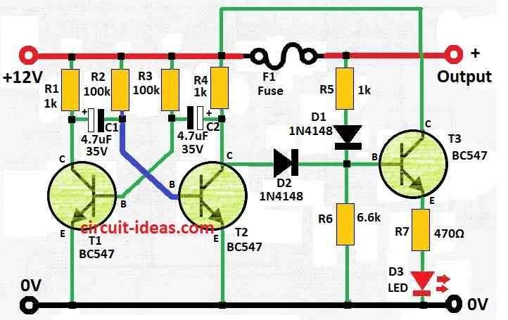
This small smart circuit for Blown Fuse Indicator Circuit with Flashing LED got one blinking LED like little spy for the electronics.
When all seems good an LED will stay bright.
But if fuse go bad maybe too much power or something weird then the LED will start blinking like party light.
That mean something is not right then its time to look and maybe change the fuse.
This circuit uses parts like resistors, one transistor and a LED to watch the fuse and lets one know when problem is coming.
Circuit Working:

Parts List:
| Component | Quantity |
|---|---|
| Resistors | |
| 1k | 3 |
| 100k | 2 |
| 6.6k | 1 |
| 470Ω | 1 |
| Capacitors | |
| Electrolytic 4.7µF 35V | 2 |
| Semiconductors | |
| Transistors BC547 | 3 |
| Diodes 1N4148 | 2 |
| LED 5mm 20mA | 1 |
| Fuse | 1 |
This circuit keeps a constant watch on DC fuse.
If fuse is okay an LED will stay ON all time.
But if fuse breaks then the LED will start blinking.
Its made for 12V first but if required one can change for other voltage.
For 6V make all resistors half and for 24V make them double.
The circuit uses around 25 mA which mostly go to the LED.
If want to use with battery stuff then it is better to use bright LED that do not require much power.
Also one can change R7 to match that.
Formula:
This circuit use astable multivibrator to show if fuse is blown by using one LED that blink.
How it blink?
The blinking speed (frequency) come from resistors (R1, R2, R3) and capacitors (C1, C2) in the circuit design.
Formula is:
f = 1.44 (R1 + 2 * R2) *C1
where,
- R1 and R2 go to transistor base
- C1 connect between base and collector of one transistor that is linked to one transistors base and collector.
Blinking LED:
When multivibrator change state the LED goes ON and OFF as it blinks.
Blink speed depends on frequency of multivibrator.
Circuit diagram help to find faulty fuse fast and LED blink mean fuse is blown.
If required one can change parts values and test until it work best.
How to Build:
To build a Blown Fuse Indicator Circuit with Flashing LED follow the steps mentioned below:
Get All Parts:
- Take all needed parts like in the circuit diagram shown above.
Make Layout:
- Plan how to put parts on breadboard or PCB.
- Leave good space and follow wire paths.
Start Assembly:
- First solder resistors and other small parts.
- Look careful at resistor values and where one needs to put them.
Add Transistor:
- Solder transistor next.
- Be sure it faces the right way like in diagram.
Connect LED:
- Now put LED connect anode (long leg) to positive and cathode (short leg) to negative.
- Use bright LED if circuit on battery is required.
Add Fuse:
- Connect fuse holder in circuit.
- Be sure fuse is in right place and rating is correct for ones work.
Test Circuit:
- Before closing circuit test it.
- Power it up and LED should stay ON if fuse is OK.
- If fuse breaks then LED should blink.
Change for Other Voltages:
- If not using 12V then use for 6V use half resistor values and for 24V use double values.
Finish Build:
- After test is OK and volt has changed then finish soldering.
- Check all wires are tight and no shorts circuits.
Put in Box (Optional):
Final Check:
- Before actual use test it again.
- Check if it work right.
Install:
- Now put the circuit in the project.
- Connect it with power and device that fuse protects.
Conclusion:
Blown Fuse Indicator Circuit with Blinking LED is used in many electronic things where watching fuse is important for safety and fixing.
It help to know fast when fuse go bad and no need to check fuse by hand.
This save time and make fixing easy and quick.
Leave a Reply