In this article for Simple Decimal Counter Circuit instead of count in binary (0 to 1) the decimal counter count in base is 10 (0 to 9).
One simple and main way to make it:
Use Decade Counter IC which is good for beginners.
The IC like 4017 is easy to find and can already count 0 to 9.
Its easy to use and need less extra parts.
IC does the main counting.
We may still need resistors and LEDs to show numbers.
For most actual use this method work better.
Circuit Working:
Parts List:
| Component | Description | Quantity |
|---|---|---|
| Resistors | 220Ω 1/4 watt | 1 |
| 1k 1/4 watt | 1 | |
| Capacitor | Ceramic 100nF | 1 |
| Semiconductors | IC 4017 | 1 |
| Push button | 1 | |
| LEDs Red 5mm 20mA | 8 |
This article uses IC 4017 to explain how decade counter circuit work.
Decimal Counting Circuit:
This circuit count things like button press which is not just 0 and 1 like computer.
It count from 0 to 9 like in base 10.
How to Build:
Use IC 4017 is easy and is in beginner friendly way.
IC is made for decimal count and need less extra parts.
IC does the counting job inside.
How It Works:
Clock signal like button press, it starts the count.
Each press increases the count which is shown by LEDs.
Pin Information:
Each pin have job:
- Pin 12 carry out and connect many counters together.
- Pin 13 clock enable pin controls when to count.
- Pins 3, 2, 4, etc. show count in binary.
- Clock input where count signal comes in.
- Binary output need decoder to power LED display.
Reset:
There is reset feature to make count go back to zero anytime.
Main Idea:
Decade counter count in base-10.
We can build with logic gates but easier way is to use IC like 4017.
Formulas:
LED Formula for Decimal Counter with IC 4017.
LED Current Limit:
Resistor with LED control how much current goes through LED.
Use ohms law: R = V / I
where:
- V is the supply voltage for LED forward voltage
- I is the current for LED which is usually 20mA
Example Formula:
If supply is 5V then LED drop is 2V and desired current is 20mA:
R = (Vsupply − VLED) / ILED
= (5V − 2V) / 0.02A = 150 ohms
Explanation:
Vsupply is the voltage from battery or power source
VLED is the voltage drop of LED which depends on LED color/type
Red LED is around 1.8 to 2.2V
ILED is wanted current which is mostly 20mA for standard LED
Note:
Choose resistor carefully.
If current is too high then LED can burn.
Right resistor keeps LED safe and works long time.
How to Build:
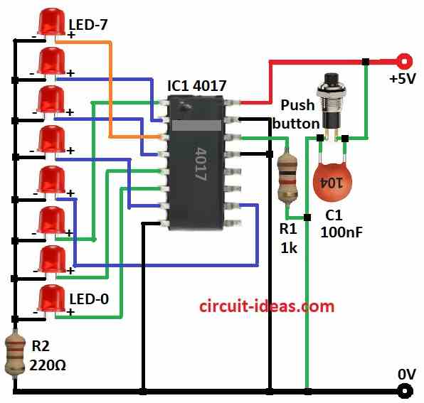
To build a Simple Decimal Counter Circuit follow the below mentioned steps for connections:
- Pin 1 of IC 4017 connects to anode of LED 2
- Pin 2 connects to anode of LED 6
- Pin 3 connects to anode of LED 7
- Pin 4 connects to anode of LED 5
- Pin 5 connects to anode of LED 1
- Pin 6 connects to anode of LED 0
- Pin 7 connects to anode of LED 4
- Pin 10 connects to anode of LED 3
- Pins 8, 13, 15 connects to ground
- Cathode of LEDs 0 to 7 connects to ground through resistor R2
- Pin 14 connects to one side of push button through Resistor R1
- Other side of push button connects to +5V supply
- Capacitor C1 connect across push button terminals
Safety Tips:
- Start with simple circuit and make it harder slowly as we learn.
- Before power ON, check all wire and parts are connected right.
- Label wires and parts which makes fixing easy.
- Keep fire extinguisher nearby just in case.
- Ask expert if we are not sure about safety or circuit.
Conclusion:
This Simple Decimal Counter Circuit counts from 0 to 9 (base-10).
We can build with logic gates or use IC 4017 which is the easier way.
Always follow safety rules when working with electronics.