When ON, small device like Simple Door Keyhole Light Circuit gives light to keyhole.
It helps to put key in hole when light is low.
It uses light sensor and circuit to check light level.
To switch it by light we used transistor and LDR.
Circuit Working:
Parts List:
| Category | Item | Quantity |
|---|---|---|
| Resistors | 47k 1/4 watt | 1 |
| 2.2k 1/4 watt | 1 | |
| LDR | 1 | |
| Semiconductors | Transistor BC547 | 1 |
| LED green 5mm 20mA | 1 | |
| 9V battery | 1 |
After making this circuit we can fix it inside any lock keyhole.
It has special sensor like LDR that checks light around.
In dark LDR resistance goes up and in bright light the resistance goes down.
Circuit uses two resistors one normal and other one LDR to make a voltage divider.
When its dark the LDR resistance is high and switch the transistor turns ON and LED lights up.
This light helps us see keyhole at night.
So this small circuit works like auto nightlight for keyhole and makes opening door in dark easy.
Formulas:
To make simple keyhole light circuit use this formula:
R1 base resistor for BC547:
Controls current to transistor base.
Base current IB = Collector current (IC) ÷ transistor gain (β).
Use small current around 10mA for LED.
BC547 transistor gain (β) is between 200 to 800.
Formula:
R1 = (VCC − VBE) ÷ IB
where,
- VCC is 9V and
- VBE is 0.7V
R2 resistor for LED current limit:
Keeps LED current safe to max 20mA.
Formula:
R2 = (VCC − VLED) ÷ ILED
where,
- VLED for green LED is 2V
- ILED is 20mA
Choose R1 and R2 values based on our parts and how we want circuit to work.
How to build:
To build a Simple Door Keyhole Light Circuit follow the below mentioned steps for connections:
Steps to Build Circuit:
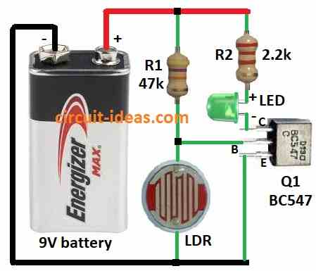
- Collect all parts shown in circuit diagram.
- Connect transistor Q1s collector to positive through resistor R2 and green LED.
- Connect transistor Q1s base between resistor R1 and LDR.
- Connect emitter of Q1 to ground.
- Connect 9V battery positive to circuits positive and negative to ground.
Safety Tips:
- Work on flat and stable place.
- Use correct tools.
- Do not touch live wires.
- Use right battery.
- Keep away from kids and pets.
Conclusion:
This small and Simple Door Keyhole Light Circuit helps light up keyhole in dark.
It works auto using LDR and transistor.
It helps us find keyhole and open door at night easily.
Leave a Reply