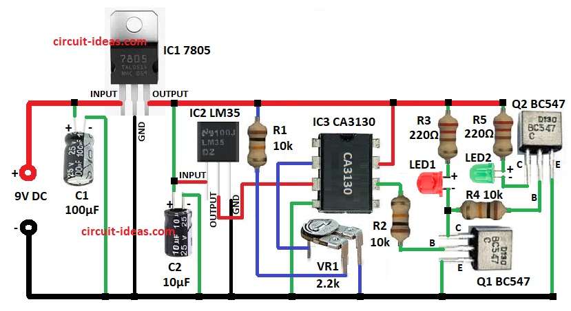
Dual LED Temperature Indicator Circuit light one LED when hot and other when cold.
It uses IC LM35 temperature sensor, CA3130 op-amp and two BC547 transistors.
IC 7805 change 9V to steady 5V and if there is 5V already then we can connect directly.
IC LM35 gives 10mV more for every 1°C rise.
Output goes to op-amp input.
This circuit is good for showing temperature without fancy display.
Circuit Working:
Parts List:
| Component Type | Value | Quantity |
|---|---|---|
| Resistors (All resistors are 1/4 watt unless specified) | 10k | 3 |
| 220Ω | 2 | |
| Preset 2.2k | 1 | |
| Capacitors | Electrolytic 100µF 25V | 1 |
| Electrolytic 10µF 25V | 1 | |
| Semiconductors | IC 7805 Voltage Regulator | 1 |
| IC LM35 Temperature Sensor | 1 | |
| IC CA3130 Op-Amp Comparator | 1 | |
| Transistors BC547 | 2 | |
| LED Red 5mm 20mA | 1 | |
| LED Green 5mm 20mA | 1 |
9V DC change to steady 5V by IC1 7805.
IC2 LM35 give voltage same as temperature.
LM35 output goes to non-inverting input of op-amp CA 3130 which is IC3.
Inverting input get reference voltage from preset VR1.
Example: set VR1 to 0.8V and then IC LM35 output reaches 0.8V at 80°C.
Then IC3 output will go high and turn ON Q1 and red LED1 will light.
Q2 base connects to Q1 collector and so Q2 goes OFF and green LED2 will go dark.
If temp goes below 80°C then reverse will happen.
Formulas with Calculations:
Below are the formulas with calculations for Simple Dual LED Temperature Indicator Circuit:
Vref set by R1 and VR1:
Vref = (VR1 / (R1 + VR1)) × Vcc
where,
- R1 is 10k
- VR1 is 2.2k
- Vcc is 5V
Vref = (2.2 / 12.2) × 5 = 0.9V
If LM35 output is more than 0.9V then about at 90°C circuit will trigger.
How to Build:
To build a Dual LED Temperature Indicator Circuit follow the below mentioned steps for connections:
- Collect all parts as in circuit diagram.
- Connect IC1 7805 pin 1 to 9V DC, pin 2 to ground and pin 3 connect to pin 1 of IC2 LM35.
- Connect C1 positive to IC1 pin 1 and to ground.
- Connect IC2 GND to ground and connect IC2 output to pin 3 of IC3 CA3130.
- Connect C2 positive to line between IC1 output and IC2 input and to ground.
- Connect R1 from IC1 output to VR1 one side and connect VR1 middle pin to IC3 pin 2 other pin to ground.
- Connect IC3 pin 4 to ground and pin 6 connect to Q1 base through R2 and pin 7 connect to positive supply.
- Connect Q1 collector to red LED1 cathode and LED1 anode connect to R3 and R3 connect to positive supply.
- Connect Q1 emitter to ground.
- Connect R4 from Q1 collector to Q2 base and connect Q2 emitter to ground.
- Connect Q2 collector to green LED2 cathode and LED2 anode connect to R5 and R5 connect to positive supply.
Conclusion:
This Dual LED Temperature Indicator Circuit is easy, precise and good for temperature monitoring.
ICs LM35 and CA3130 gives accurate switch.
Circuit is simple to build and is important for temperature control.