This project is for Simple Gold Detector Circuit and it uses magnet and electric to find metal and even gold.
Here, the electric goes fast back and forth and this make magnetic field in coil; and when metal come close then electric changes.
Also, it is an fun project to learn about metal detector but may not that good for real treasure.
Circuit Working:
Parts List:
| Components | Values | Quantity |
|---|---|---|
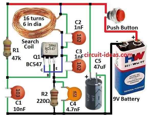
| Resistors (All resistors are 1/4 watt unless specified) | 47k | 1 |
| 220Ω | 1 | |
| Capacitors | Ceramic 10nF | 1 |
| Ceramic 4.7nF | 1 | |
| Ceramic 1nF (each) | 2 | |
| Electrolytic 47µF 25V | 1 | |
| Semiconductors | Transistor BC547 | 1 |
| Inductors/Coils Search Coil 16 turns, 6″ diameter (12cm) | 1 | |
| Switch button | 1 | |
| 9V Battery | 1 |
This is simple metal detector circuit which can find gold, coins and other metal, but it does not work like big pro detector.
How it work:
Circuit make fast magnetic field around coil with about 140 kHz and when metal come close it make eddy current in metal; hence, this changes coil inductance so circuit frequency changes.
AM radio hear this as squeal or beat sound and when metal closes squeal tone changes.
Things to know:
Circuit only work with few centimeters depend on metal size and type, also may get false signals from ground or other stuff.
Radio must tune near harmonic of oscillator and there is no real station but just listen for beat sound.
Coil is 6 turns and 12 cm round and we can change this to test better.
Furthermore, the circuit uses battery with low voltage and is safe to use but be careful while handling all electric things.
Also, this project is good for learning how metal detector work., but do not expect it to find treasure like real detector!
Formulas:
To make simple gold detector circuit, first step is make sensitive oscillator and it must feel small change in ground from metal like gold.
Basic formula for frequency (f):
Moreover, this uses LC tank circuit like L is coil as inductor and C is capacitor and when coil goes near gold or metal the L changes that makes frequency change.
Formula:
f = 1 / (2π √(L × Ceq))
- L is the coil inductance
- Ceqis the total equivalent capacitance
Note:
Hence, this formula help understand how gold detector work; resistors, capacitors and coil all are important and to get good results circuit needs careful tuning and setup.
How to Build:
To build a Simple Gold Detector Circuit follow the below mentioned steps:
- First, connect base of Q1 to R1 47k resistor then to positive side of battery, connect collector of Q1 to C2 and C3 with 1nF capacitors and then to positive side of battery and then connect emitter of Q1 to R2 resistor and then to negative side of battery.
- Then connect R1 and C1 in series from positive to negative supply.
- After that, connect search coil one side to Q1 collector and other side to positive supply.
- Now connect push button to positive battery supply and also connect C5 capacitor from positive to negative supply.
Note:
- This circuit runs on a low-voltage battery supply, which makes it generally safe; however, always exercise caution while building it.
Conclusion:
To conclude, this Simple Gold Detector Circuit use magnetic field to find the metal, as it can detect gold and other metals but only nearby.
Additionally, not good at telling what type of metal it is or ignoring the ground noise, but still it is an fun project and good to learn how metal detectors work!
Leave a Reply