A powerful metal detector circuit typically features high sensitivity and the ability to detect a wide range of metal types at varying depths.
The coil is a crucial component of the metal detector.
A large coil can detect objects at greater depths, but smaller coils provide better sensitivity to small objects.
Interchangeable coils are ideal for versatility.
Circuit Working:
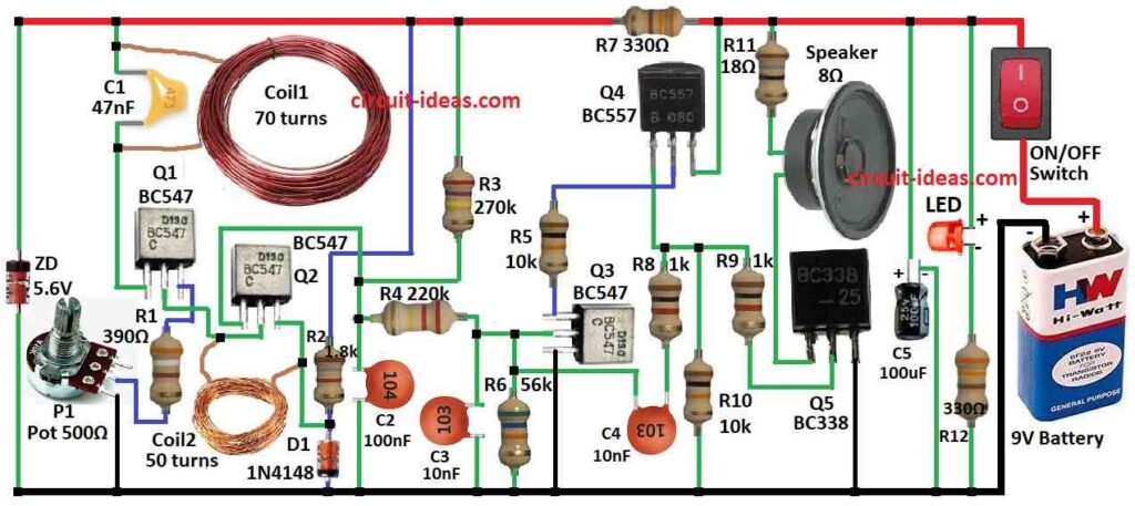
Parts List:
| Component Type | Description | Quantity |
|---|---|---|
| Resistors (All resistors are 1/4 watt unless specified) | 390Ω | 1 |
| 1.8k | 1 | |
| 270k | 1 | |
| 220k | 1 | |
| 56k | 1 | |
| 18Ω | 1 | |
| 330Ω | 2 | |
| 1k | 2 | |
| 10k | 2 | |
| Potentiometer | 500Ω | 1 |
| Capacitors | Ceramic 47nF | 1 |
| Ceramic 100nF | 1 | |
| Ceramic 10nF (each) | 2 | |
| Electrolytic Capacitor | 100µF 25V | 1 |
| Semiconductors | Transistor BC547 (each) | 3 |
| Transistor BC557 | 2 | |
| Transistor BC338 | 2 | |
| Zener diode 5.6V | 1 | |
| Diode 1N4148 | 1 | |
| Coils | 70 turns (see text) | 1 |
| 50 turns (see text) | 1 | |
| LED | any 5mm 20mA | 1 |
| Speaker | 8Ω | 1 |
| Switch | ON/OFF Switch | 1 |
| Battery | 9V | 1 |
There are several methods to identify a metal object and adjust a circuits function to generate an output.
Metal detectors can detect ferrous (iron, steel, stainless steel) and non ferrous (copper, tin, gold, lead, silver, aluminum) metals, as well as alloys (brass, cupro nickel, pewter, etc.).
Depending on the circuits complexity a metal detector can differentiate between a gold nugget and an aluminum ring pull from a drink can.
The circuit presented in this project is simple and operates based on detecting waveform amplitude known as amplitude modulation AM.
When a metal object enters the detection coil some magnetic flux passes into it generating an eddy current.
This current consumes some flux reducing the available flux for the receiving coil.
Consequently, the coils output decreases causing the second transistor in the circuit to partially turn off increasing the voltage at the collector.
This change allows the third and fourth transistors to oscillate sending a signal to the fifth transistor to drive a mini speaker.
Although both the amplitude and frequency of the circuit change when detecting a metal object the focus is on the reduced amplitude.
The circuit comprises various building blocks.
Understanding each blocks operation helps comprehend the entire circuit.
The aim of this circuit is to explain these building blocks so that you can design your projects.
The first coil and capacitor create a tuned circuit.
When a metal object approaches the coil the oscillations amplitude decreases.
The second coil amplifies this signal.
For instance, a 1mV reduction in the main oscillators amplitude leads to a 70mV reduction at the second coil causing the second transistor to slightly turn off creating a buzz in the speaker.
- This block includes the first transistor, 70 turn coil, 47n capacitor and 50 turn coil.
- The first transistor turns on through a diode in the second transistors emitter receiving bias from a 1.8k resistor.
- The tuned circuit has a frequency of about 15kHz stabilized by a 5.6V zener.
Voltage Controlled Oscillator VCO:
- Consisting of transistors 3 and 4, the VCO is a high gain amplifier with a 10nF feedback capacitor for oscillation.
- When a voltage appears at the base of the third transistor, it turns on triggering the PNP transistor and causing the 10nF capacitor to charge, creating a variable frequency oscillator.
Driver Transistor:
- This block connects the oscillators output to a driver transistor which is directly connected to an 8 ohm speaker producing a clicking sound.
Additional Note:
For this circuit to work well the supply voltage must be stable as it detects small amplitude changes affected by voltage fluctuations.
The use of a zener diode for supply stability is crucial but temperature changes can affect circuit settings, causing instability.
While the circuit is simple, it offers good sensitivity and an audio output.
Metal detectors have various industrial applications such as detecting metal particles in food, hidden objects on individuals distinguishing between iron compounds and gold and detecting coins for vending machines.
To experiment with different coil sizes and shapes start with the supplied coils and make small adjustments to avoid circuit failure.
Changing coil diameters affects penetration depth requiring more energy and a higher supply voltage.
Conduct these experiments carefully and take extra care while operating with the electrical items specially with the beginners.
Formulas:
In order to build a potent metal detector circuit, one must first design a sensitive oscillator capable of identifying variations in the electromagnetic field brought on by adjacent metal objects.
Here is a basic formula:
The frequency oscillator (f):
The LC tank circuit made up of the search coil (inductor ) and capacitors C largely determines the oscillation frequency f:
f = 1 / 2π√L * C
where,
- L is the search coils inductance.
- The oscillator circuits capacitance is denoted by C.
This overview and formula provide you a basic grasp of how to create a potent metal detector circuit.
To maximize performance for successfully detecting different types of metals, more thorough design and testing would be necessary for the individual implementation details, such as component values and circuit structure.
How to Build:
To build a powerful metal detector circuit follow the below mentioned steps:
Prepare the PCB:
- If you are using a kit follow the instructions to prepare the PCB.
- If you are building from scratch design and etch a PCB or use a breadboard for testing.
Assemble Components:
- Solder the components onto the PCB according to the schematic diagram.
- Place the coils transmitting and receiving on the PCB as per the design.
Connect the Power Source:
- Connect the positive and negative terminals of the power source e.g. 9V battery to the PCB as the schematic.
Test the Circuit:
- Before closing the enclosure test the circuit to ensure it is functioning correctly.
- Use a metal object to test the detectors sensitivity and range.
Adjust Settings:
- If your circuit has adjustable settings sensitivity frequency etc., adjust them to optimize performance.
Calibrate the Detector:
- Fine tune the detectors settings based on your environment and target metal types.
Use and Maintain:
- Use the metal detector according to its specifications.
- Regularly check and maintain the circuit for optimal performance.
Conclusion:
Building a powerful metal detector circuit involves assembling the necessary components soldering them onto a PCB connecting a power source, testing the circuit and fine tuning its settings for optimal performance.
While the process requires basic electronics skills, it can be a rewarding project for hobbyists and enthusiasts interested in metal detection.
Leave a Reply