This easy Heads or Tails Decision Maker Circuit show how to make fun coin flipper using electric.
Like when we flip real coin but here we press a button and small chip inside do fast thinking and then say “heads” or “tails” very quickly
It uses logic parts and small electric pieces to give random answer.
It is a fun and interesting way to solve small problems.
Circuit Working:
Parts List:
| Category | Component | Quantity |
|---|---|---|
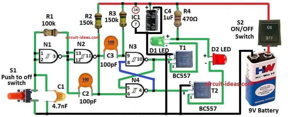
| Resistors | 100k 1/4 watt | 1 |
| 470Ω 1/4 watt | 1 | |
| 150k 1/4 watt | 2 | |
| Capacitors | Ceramic 4.7nF | 1 |
| Ceramic 100pF | 2 | |
| Electrolytic 1µF 25V | 1 | |
| Semiconductors | Transistors BC557 | 2 |
| IC4093 (N1 to N4) | 1 | |
| LEDs Red / Green | 2 | |
| Switches ON / OFF Switch | 1 | |
| Push to OFF Switch | 1 | |
| Battery 9V | 1 |
Flip flop using N3 and N4 with N2 is working from square wave maker made by gates N1, R1 and C1.
Transistors T1 and T2 take output from flip flop and turn ON LEDs D1 and D2 one by one.
When button is pressed both LEDs blink fast.
After pressing one LED stay ON and other become OFF.
These LEDs called “heads” and “tails” to give random decision.
At first one more LED was planned but later removed because people now are smart and can decide by themselves.
This circuit is very sensitive so it gives true and random result for heads or tails.
Many hobby circuits are there but this one is shown here.
Formulas:
We make simple formula for NAND gate oscillator to guess the frequency (f) under some thinking:
Charging and draining time are same.
This means resistor and capacitor have same value in both ways (R1 = R2, C1 = C2).
NAND gate works perfect.
We ignore small delay inside the gate.
So using these ideas the formula is:
f = 1.44 / (R * C)
where:
- f is how many times it goes ON/OFF in 1 second like in Hz
- R is the resistor value in ohms Ω
- C is the capacitor value in farads F
How to Build:
To build a Heads or Tails Decision Maker Circuit follow the below mentioned connections steps:
- Put the silicon chips on breadboard and use them to make digital logic gates.
- Connect input and output as needed.
- Use Gates N1, resistor R1 and capacitor C1 to build square wave generator.
- This will control the flip flop.
- Use NAND gates N3 and N4 to make flip flop.
- Be sure it gives two different outputs one after other.
- To turn ON and OFF LEDs D1 and D2 use transistors T1 and T2.
- Connect them properly to switch lights.
- Put the push button in the circuit.
- Press it to begin the decision process.
- Give good power to the circuit.
- Use battery or any other proper power source.
- Press the button and see how LED changes.
- Check if the result looks random.
Conclusion:
This Heads or Tails Decision Maker Circuit can help in many ways like solving fights, choosing something or adding fun to games.
It is a cool use of electric parts that acts like real coin toss.