To begin with, this Line Following Robot Sensor Circuit work like robot eyes to follow line.
Furthermore, it uses special sensor called IR or infrared to see black line and white ground.
Also, these sensor are like small light but light is invisible.
Then circuit look how much light come back then know where line is and then this information goes to robot brain, so robot can turn and follow line good.
Like when we walk on footpath robot use this circuit to walk on its path.
Circuit Working:
Parts List:
| Components | Values | Quantity |
|---|---|---|
| Resistors (All resistors are 1/4 watt) | 1k | 1 |
| 4.7k | 1 | |
| 1.8k | 1 | |
| 200Ω | 1 | |
| Preset 10k | 1 | |
| Capacitors | Electrolytic 10µF 25V | 2 |
| Semiconductors | Transistors BC547 | 2 |
| Phototransistor CNY70 | 1 | |
| LED Red 5mm 20mA | 1 |
A Line Following Robot uses a sensor that works like a small scanner and fits into a package about the size of a postage stamp.
The sensor uses short-range infrared detection with a range of about 5 to 10 mm and the CNY70 chip contains this sensor inside.
In robots or toy cars this sensor help follow black line on white floor and keeps robot on right path.
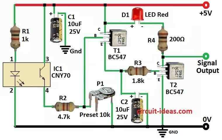
Here, CNY70 chip have two parts one is IR LED which gives light and other one is phototransistor to see light.
LED send out invisible light to floor and phototransistor can see how much light comes back.
White surface send more light back and black send less, so when robot is on white floor more current goes through phototransistor.
Hence, when sensor see light come back current go through resistor R2 to ground then this make voltage drop at transistor T1 base and T1 start working.
Then transistor T2 also turn ON and this make red light LED D1 turn ON and capacitor C2 help a little by making signal smooth.
After we build the scanner we need to set it up.
First, turn knob P1 to middle and put robot on white part of line
After that, move P1 slow until red LED D1 shine bright and after that change P1 small more to stop fake signal from sunlight or other light.
Be sure LED stay OFF when robot is over black line and do this many time until sensor work good.
Red LED D1 only show light to tell that sensor is working.
Further, if we want more feature then can add small 5V relay near D1 and R4 and then robot can stop, brake or change the direction.
Also, when T2 switches ON and OFF and generates an H-to-L signal, the circuit can use this signal to control the robots brain.
Finally, resistor R1 control how much power goes to IR LED in chip and how well sensor work depends on black/white line quality and LED brightness.
How to Build:
To build a Line Following Robot Sensor Circuit follow the below mentioned assembling steps:
- First, solder all parts on PCB same like in circuit diagram.
- Next, check CNY70 datasheet to know which pin goes where and which side is front.
- Now give 5V power to the circuit.
- Then put the sensor in place and set it up like told before like the calibration steps.
Conclusion:
Overall, Line Following Robot Sensor Circuit is important part for robot that follow line, as it uses infrared sensor to see line on floor.
Also, sensor send and catch back IR light and this tell robot where line is, so robot can move correct way.
Finally, this technique help robot go on path by itself and it is useful for many things like factory work, school projects and in fun robot toys.