Compared to basic circuit this Long Range IR Transmitter Circuit can send IR light farther using easy parts.
Main idea is to make IR LED blink light in pulses.
Most IR receivers catch specific frequency made by IC 4047.
Using more LEDs together or stronger LED gives more IR light, so with better range.
This circuit can send IR light up to 100 cm more.
So we can use long range IR circuit to increase IR distance many times.
Circuit Working:
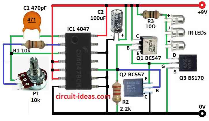
Parts List:
| Category | Item | Quantity |
|---|---|---|
| Resistors | 10k 1/4 watt | 1 |
| 2.2k 1/4 watt | 1 | |
| 10Ω 1/4 watt | 1 | |
| Potentiometer 10k | 1 | |
| Capacitors | Ceramic 470pF | 1 |
| Electrolytic 100μF 25V | 1 | |
| Semiconductors | IC 4047 | 1 |
| Transistor BC547 | 1 | |
| Transistor BC557 | 1 | |
| MOSFET BS170 | 1 | |
| IR LED transmitter | 3 |
Increase IR Power:
This circuit make IR light go more far.
We uses 3 IR LEDs in series and this gives more IR light.
RC Combo and Frequency:
On pin 2 and 1 of 4047 IC we have connected resistor and capacitor.
They make circuit blink fast like ON-OFF switch.
This blinking goes to transistor Q1 and Q2.
Why Frequency Matter:
We use 4047 IC because it gives 38 KHz signal.
Many remotes use same frequency.
We mix our data with 38 KHz signal so IR light become strong and clear.
MOSFET for Less Power Loss:
4047 IC also send signal to MOSFET BS170 and transistors.
MOSFET works like switch but better than normal transistor.
It save power and give better result.
Also 100uF capacitor helps stop voltage drop when turning circuit ON-OFF
Clear Signal with Darlington Pair:
BC547 and BC557 transistors work together to give clean signal to MOSFET gate.
This fix signal problem that can happen with MOSFET.
Longer IR Distance:
MOSFET drain connect to 3 IR LEDs.
When gate gets signal, current flows and LEDs light up.
This setup sends IR light much farther than normal IR circuit.
So IR receiver can catch signal from more distance.
Formula:
IC 4047 in astable mode uses 1 resistor R and 1 capacitor C.
We can find frequency using this easy formula:
Frequency = 1 / (8.8 × R × C)
where:
- Frequency is how fast it blinks in Hz
- R is resistor value in ohms Ω
- C is capacitor value in farads F
If we know R and C then we can use this formula to find the blinking speed of the circuit.
How to Build:
To build a Long Range IR Transmitter Circuit follow the below mentioned steps for connections:
- Gather all parts like in circuit diagram.
- Connect pin 1 to pin 3 of IC 4047 through capacitor C1 and also connect to one leg of 10k pot P1.
- Connect pin 2 to pot through resistor R1.
- Connect pin 4, 5, 6, 14 to +9V supply.
- Connect pin 7, 8, 9, 12 to ground.
- Connect pin 10 to base of transistor Q2.
- Collector of Q1 goes to +9V and base of Q1 goes to ground through resistor R2 and emitter of Q1 connects with emitter of Q2.
- Base of Q2 goes to pin 10 and collector of Q2 to ground and emitter to emitter of Q1.
- Connect capacitor C2 from +9V to ground.
MOSFET Q3:
- Drain goes to +9V through resistor R3 and 3 IR LEDs in series.
- Gate connects to emitters of Q1 and Q2.
- Source goes to ground.
Safety Tips:
- First test with simple circuit.
- Use good quality parts.
- Wash hands after touching components.
- Check all connections before turning ON the power.
- Be careful to avoid accidents.
Conclusion:
By using many IR LEDs and correct blinking frequency this Long Range IR Transmitter Circuit sends IR signal far.
Darlington pair gives clean signal and MOSFET makes it efficient.
Always follow safety rules when building and using this circuit.
Leave a Reply