
This article presents a simple PIR sensor timer circuit using transistors; the circuit costs little, is easy to build, and operates from a 12 V DC power supply.
When the PIR sensor detects motion, the output stays ON for a preset time and then turns OFF automatically after the delay, hence, this feature makes the circuit useful for lighting, alarm, and automation projects.
Circuit Working:
Parts List:
| Components | Values | Quantity |
|---|---|---|
| Resistors | 4.7k | 2 |
| 1k, 1M | 1 each | |
| Capacitor | Electrolytic 330uF 25V | 1 |
| Semiconductors | Transistor 2N2222 NPN | 1 |
| Transistor 2N2907 PNP | 1 | |
| Diode 1N4148 | 1 | |
| Sensor Module PIR Motion Sensor | 1 | |
| LED any color | 1 | |
| Power Supply 12V DC | 1 |
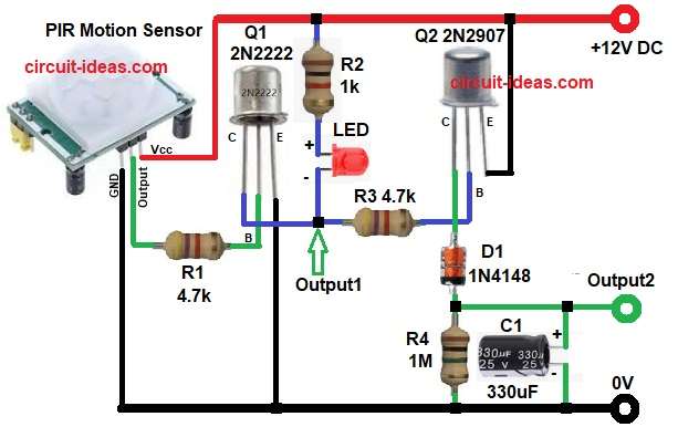
This circuit starts first with PIR sensor detects motion, then PIR output goes HIGH and this signal passes through resistor R1, which turns ON transistor Q1.
When Q1 turns ON the current flows from collector to emitter and then LED1 glows through resistor R2 and this shows motion detected.
Transistor Q1 turns ON the moment the system detects motion, pulling Output 1 LOW instantly and when motion ceases, transistor Q1 turns OFF, which causes Output 1 to go HIGH.
At the same time, signal reaches base of transistor Q2 via R3 and then Q2 is a PNP transistor and so it turns ON when base goes LOW.
When transistor Q2 turns ON, capacitor C1 starts charging through diode D1 and resistor R4 and during this time, output 2 remains HIGH.
After the PIR output goes LOW, transistor Q1 turns OFF and however, capacitor C1 remains charged, so it keeps transistor Q2 ON for a short time.
Slowly, capacitor C1 discharges through R4 and when voltage drops transistor Q2 turns OFF and then output2 goes LOW and therefore, this creates the time delay function.
Formula with Calculation:
Timer delay mainly depends on resistor R4 and capacitor C1.
Simple formula is:
Time delay T = R × C
here,
- R value is 1M ohm
- C value is 330uF
First convert microfarad to farad.
330uF becomes 0.00033F
Now we can calculate:
T = 1,000,000 × 0.00033
T = 330 seconds
So delay time is around 5 to 6 minutes and actual delay can change little bit.
How to Build:
To build a Simple PIR Sensor Timer Circuit using Transistors follow the below steps for connection:
- First, collect all the parts as shown in circuit diagram.
- Next, PIR Sensor V+ pin connects to +12V, V- pin connects to GND and out pin connects to R1.
- Then transistor Q1 2N2222 base pin connects to R1, emitter connects to GND and collector connects to output1, LED1 cathode and R2 in series and LED1 anode connects to one end of R2 and other end of R3 connect to positive supply.
- After that, transistor Q2 2N2907 emitter pin connects to +12V, base pin connects to R3 and collector connects to anode of diode D1, also, cathode of D1 connects to output2 and capacitor C1 positive and one end of resistor R4.
- Now capacitor C1 positive pin connects to output2 and negative pin connects to GND.
- Further, resistor R4 one side connects to output2 and other side connects to GND.
- Finally, power supply positive supply connects to +12V rail and negative connects to GND rail.
Conclusion:
To conclude, this Simple PIR Sensor Timer Circuit using Transistors is very reliable, as it uses easily available components and it gives adjustable delay by changing R4 or C1.
Also, it is suitable for beginners and hobby projects and at last, we can use it for lights, alarms or relays.