This article for Simple Positive Voltage to Negative Voltage Converter Circuits shows how to change positive DC voltage to negative DC voltage using special converter circuit; also this circuit is useful for many electronic things.
One popular and easy way to generate a clock signal is to use the IC 555; also this reliable IC works well in astable mode, where it generates a square-wave signal by continuously switching its output voltage.
Circuit Working:
Parts List:
| Components | Values | Quantity |
|---|---|---|
| Resistors (All resistors are 1/4 watt unless specified) | 4.7k | 1 |
| 33k | 1 | |
| Capacitors | Ceramic 0.022μF | 1 |
| Ceramic 0.01μF | 1 | |
| Electrolytic 22μF 25V | 1 | |
| Electrolytic 100μF 25V | 1 | |
| Semiconductors | IC 555 | 1 |
| Diodes IN4001 | 2 |
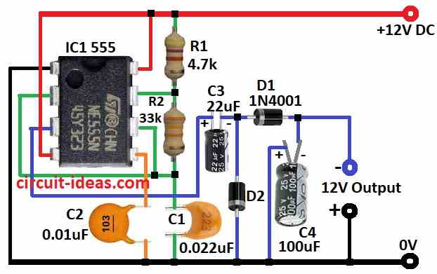
In this circuit IC 555 work as astable multivibrator, as it change +12V to -12V and make square wave again and again; also this square wave run a switching part using resistors, capacitors and diodes to make negative voltage.
Circuit tested on Vero board to show how to get negative voltage from positive source, also it look like dual power supply by using both +12V and -12V.
Here, negative voltage is always with few volts less than positive one.
Furthermore, IC 555 serves as the main component in this circuit and operates at approximately 1 kHz, then place the IC in a socket, and after that pin 3 outputs a square wave signal.
Capacitor C3 charges through diode D2 when output is high and when output goes zero then C3 discharges and C4 charge through D2.
So use capacitors C3 and C4 with 25V rating or more and do not connect load more than 50 mA and finally, always get negative voltage at point between C4 cathode and D1 anode and compare to ground.
Formulas:
To make positive to negative voltage converter we must choose right parts and do some calculations, as this gives needed formulas to build our own circuit.
When IC 555 work in astable mode with two resistors R1, R2 and one capacitor C which decide the output frequency.
Formula:
f = 1.44 / (R1 + 2 × R2) × C
where,
- R1 and R2 in ohms
- C is in farads.
Capacitor Value C:
Capacitor helps clean the output voltage and reduces ripple, so formula to find output capacitor Cout:
Cout = Iout × D × (1 – D) / f × ΔVout
where:
- Iout is the output current
- ΔVout is the ripple voltage we allow
Therefore, by using these formulas we can make and change the converter to match our need.
How to Build:
To build a Simple Positive Voltage to Negative Voltage Converter Circuit we need to follow the below mentioned steps:
- First, collect all parts shown in circuit diagram.
- Next, connect pin 1 of IC 555 to ground.
- Then connect pin 2 to pin 6.
- After that, connect pin 3 to -12V output using capacitor C3 and diode D1.
- Now connect pin 4 and pin 8 to +12V supply.
- Also, connect pin 5 to ground using capacitor C2.
- Then put resistor R2 between pin 6 and pin 7 and capacitor C1 to ground and connect resistor R1 from pin 7 to +12V.
- Put diode D2 between C3 and D1 and ground and then connect capacitor C4 between D1 and -12V output and then to ground.
Conclusion:
To conclude, this Simple Positive Voltage to Negative Voltage Converter Circuit gives negative voltage from positive power; as it is important to understand the circuit first and use correct part ratings and add safety like insulation and fuse.
Finally, do testing and prototyping carefully to avoid problems and get reliable work.