Think about a motor which is very special.
It can turn to be very exact, this small circuit is like a brain.
It tells motor how much to turn using small electric pulses.
Long pulse motor move more then the short pulse motor move less.
We can say it what to do like move robot arm then Simple Servo Motor Controller Circuit will listen and send right pulse to motor.
Circuit Working:
Parts List:
| Category | Component | Quantity |
|---|---|---|
| Resistors | 390k 1/4 watt | 1 |
| Potentiometer 10k | 2 | |
| Potentiometer 470Ω | 1 | |
| Capacitors | Ceramic C1 0.15µF | 1 |
| Ceramic C2 0.1µF | 1 | |
| Semiconductors | IC 7555 | 1 |
| Diode 1N4148 | 1 | |
| Actuators Servo Motor | 1 |
This is simple setup for servo motor controller it uses pulse generator to control motor.
We can use CMOS IC 7555 in astable mode which make pulses to move the servo motor.
Circuit can be changed to make longer or shorter pulses.
Servo is small motor with output shaft this shaft can move to exact angle if it get right signal.
When signal stay on input line the servo hold same angle but does not move.
How long the pulse is that decides angle of shaft this is called pulse coded modulation.
Servo need new pulse every 20 milliseconds 0.02 second.
If pulse is 1.5 milliseconds then servo goes to center of 90 degree which we call it neutral position.
Shorter pulse like 1ms move servo to 0 degree with longer pulse like 2ms which move to 180 degree.
This circuit give servo the control signal.
IC1 work like astable multivibrator and makes pulses for servo to work.
10k pot VR2 with R1 and C1 decide how long pulse stays high or low.
VR2 can change high time between 2.07ms and 1.03ms but low time always remains same with 40.5ms.
VR1 help make timing more exact.
VR3 change control voltage from 1.6V to pin 5 of IC1.
If we already have outside voltage supply from 0 to10V then no need of VR3.
This control voltage tells servo where to move.
If voltage is 0V then servo will go to one end and if it is 10V it goes to other end.
If voltage is 5V then servo stay in middle.
Formulas:
IC 7555 can work in many ways.
One way is to make PWM signal to control servo motor position.
PWM means pulse width modulation.
This PWM signal from IC 7555 decides where the servo motor shaft will move.
Here is simple formula for PWM signal:
Frequency (f):
f = 1.44 / (RA + 2RB) × C
Duty cycle (D):
D = RB / (RA + 2RB)
where,
- C is the timing capacitor
- RA and RB are resistors
We can change RA and RB to fine adjust how fast frequency and how long duty the pulses are.
This will help control servo motor better with its speed or its position.
Important:
Always check if the servo motor works well with the circuit voltage and current.
First try the circuit on breadboard and then check it works good.
Then we can change parts like resistors, capacitors or potentiometer to get better performance for the servo.
This is basic idea to make servo motor controller using IC 7555.
After testing we can change values depending on how the servo moves and what we need for our project.
How to Build:
Below mentioned are the process of how to build a Simple Servo Motor Controller Circuit:
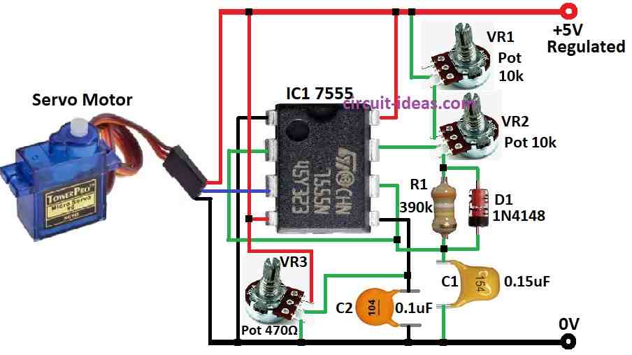
Wiring Instructions:
- Connect pin 4 and pin 8 of IC to + positive side of power supply.
- Connect pin 1 of IC to (-) negative) side of power supply that is ground.
- Join pin 2 and pin 6 together.
- Connect pin 3 to the control wire of the servo motor.
- Connect pin 7 straight to VR2 of 10k potentiometer.
- One side of R1 resistor 390Ω connects to pin 6.
- Connect pin 6 also to place where R1 and C1 capacitor 0.15µF meet.
- Connect pin 5 to one side of VR3 470Ω pot.
- Other side of VR3 connects to negative of power supply.
- Put C2 capacitor 0.1µF between pin 5 and ground (–).
- Connect positive power supply to positive wire of servo motor.
- Connect negative power supply to negative wire of servo motor.
- Again pin 3 gets connected to servo control input.
Note:
- After circuit is ready slowly adjust VR1, VR2 and VR3 to get the correct pulse width and control voltage for the servo motor to move properly.
Conclusion:
Simple Servo Motor Controller Circuit is very important when we need to move servo motor to exact position.
It makes special pulse signals to control how much servo motor turns.
Because of this we can move servo shaft very exactly.
That is why this circuit is very useful in robots, automation and other projects where we need motor to turn to right angle.